About : Series of Device Drivers for micro:bit
Contents
About...
The micro:bit is a wonderful little piece of kit. It has been designed as an educational device; being handed out freely to school children in parts of the UK.
My wife gifted me a micro:bit for Christmas a few years back. Being retired now and with a background in industrial process control and a growing interest in microcontrollers, this little device looked interesting.
However after looking at the MakeCode taught in schools I nearly binned my micro:bit. Well, not really... but I was disappointed that moving graphical blocks around on a webpage was considered in any sense "programming".
The additional on-boarded hardware; microphone, speaker, accelerometer and so on... well, one soon tires of playing with that. The two interrupt-controlled buttons and the 25-LED 'display' however do have their uses.
Then I found the MicroPython language port for the micro:bit. While not as complete as versions for other microcontrollers it never the less is serious stuff. Add a third party edge connector to the GPIO pins (should have come with the micro:bit) and a whole new world awakens.
Through the GPIO pins and MicroPython, the micro:bit can 'talk' to and control literally hundreds of other interesting things; sensors, input and output devices, electric motors and servos, and list just goes on and on.
Except for the very trivial (e.g. lighting an LED) the usual approach is to use a device driver as a starting point. And this is what this website is all about. It will provide an ever increasing list of device drivers for all sorts of things; written in MicroPython specifically for the micro:bit. They don't seem to exist elsewhere (e.g. GitHub) except with some noted exceptions. The MicroPython drivers (for the micro:bit) on this website are freely available for anyone to use (legally) as seen fit.
The Arduino is a well thought out hardware platform that is supported by a great programming environment (IDE). Just about the only gripe I have with Arduino (apart from the fact that it is 5V kit) is the way the IDE handles driver support.
Drivers are largely 'hidden' in the Arduino programming world. Drivers (source and header files) are simply linked with an 'include' to the hobbyist's program. So, arguably the most interesting part of interfacing something to a microcontroller is lost i.e. how does the interfaced device actually work? What is going on 'under the hood'?
The approach taken by this website is somewhat different. Each webpage provides a single driver for the micro:bit. The pages have two columns; the left-hand column contains the driver code and the right-hand column describes, with examples, how to use the driver code.
The driver software is prominently displayed with the hope that the user will at least attempt to understand what is happening. Python has become very popular over time. One of its true advantages over languages such as C++ is its readability.
Driver for Testing Logic Gates
The MicroPython driver accompanying this page - written specifically for the micro:bit - provides the user with a simple way to test 2-input logic gates. It is assumed that the reader understands the basics of logic gates; in any case there are plenty of online tutorials on this topic.
The driver operates specifically on 2-input positive-logic gates. It uses the GPIO pins of the micro:bit to probe and discover the truth table. From the truth table it is possible to then determine the type of logic gate under test.
The driver is able to detect all common 2-input logic gate types: AND, OR, NAND, NOR, XOR and XNOR.
Preparing the driver for use on the micro:bit
The driver can be:
- Copied from this webpage onto the clipboard then paste into the MicroPython editor e.g. the Mu Editor. It should be saved as fc_2input_logic_gate_tester.py - OR -
- Download as a zip file using the link. Unzip the file and save it as fc_2input_logic_gate_tester.py into the default directory where the MicroPython editor e.g. Mu Editor saves python code files.
After saving the fc_2input_logic_gate_tester.py file to the computer it should be copied to the small filesystem on the micro:bit. The examples on this page will not work if this step is omitted. Any MicroPython editor that recognises the micro:bit will have an option to do this.
The Mu Editor is recommended for its simplicity. It provides a Files button on the toolbar for just this purpose.
Connecting Logic Gates for Testing
This driver was tested against all gate types, predominantly with CD4000 series 2-input logic gate ICs. These chips have been around a long time - first introduced in 1968 by RCA (Radio Corporation of America) - and are inexpensive and (in most cases) still readily available.
Specifically, the following were successfully tested:
- AND : CD4081BE
- OR : CD4071BE
- NAND : CD4011BE, CD44093BE, SN74HC00N[1]
- NOR : CD4001BE
- XOR : CD4030BE, CD4070BE
- XNOR : CD4077BE
All of these chips have four individual gates of the same type. Since they are all DIP-14 packages they are easy to use on a breadboard. Another big advantage of these logic gate chips is that they share the same pinouts.


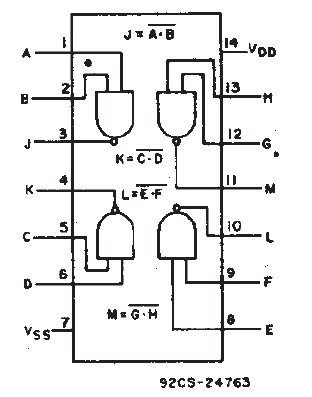
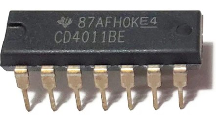
Fig 1 - CD4011BE quad 2-input NAND gate IC[2]
It is important to understand how DIP packaged chips have their pins numbered. The top of an IC has a half-moon shaped notch. Taking this as the top of the chip, pins are numbered from the top-left side downwards. Then the numbering continues from the bottom-right side upwards.
The functional diagram in Fig 1 shows the pin numbering for a DIP-14 chip. The image of the CD4011BE shows the half-moon notch that indicates the top side of the chip.
So, from the functional diagram of Fig 1 we have:
| Gate | Input 1 | Input 2 | Output |
|---|---|---|---|
| 1 | Pin 1 | Pin 2 | Pin 3 |
| 2 | Pin 5 | Pin 6 | Pin 4 |
| 3 | Pin 8 | Pin 9 | Pin 10 |
| 4 | Pin 12 | Pin 13 | Pin 11 |
Always check the product datasheet first!
From any of the CD4000 series 2-input quad logic gate chips, choose one of the four gates and connect it to the micro:bit's GPIO as shown in the following table.
| micro:bit | Logic Gate |
|---|---|
| GND | VSS (Pin 7) |
| 3.3V | VDD (Pin 14) |
| Pin 0 | Input 1 (e.g. Pin 1) |
| Pin 1 | Input 2 (e.g. Pin 2) |
| Pin 2 | Output (e.g. Pin 3) |
Testing a Logic Gate
The driver is implemented as a class. The first thing to do is call the constructor. This provides an instance of the class.
Syntax:
LGT(PINin1 = pin0, PINin2 = pin1, PINout = pin2)

Where:
  PINin1 is the first input pin of the logic gate.
  Default is to connect this pin to pin0 of the micro:bit.

  PINin2 is the second input pin of the logic gate.
  Default is to connect this pin to pin1 of the micro:bit.

  PINout is the output pin of the logic gate.
  Default is to connect this pin to pin2 of the micro:bit.

Example:
from fc_2input_logic_gate_tester import *
lgt = LGT()
The driver provides the following user methods:
- GetTruthTable()
Returns the logic gate truth table as a list of lists. Each inner list is one line of the truth table containing the two input values and the output value. - PrintTruthTable()
Outputs the truth table in a readable format. - LogicGate()
Returns the type of logic gate under test. - Report()
Outputs a formatted report comprising the truth table and the gate type. In most cases this is the only method that the user will need to call.
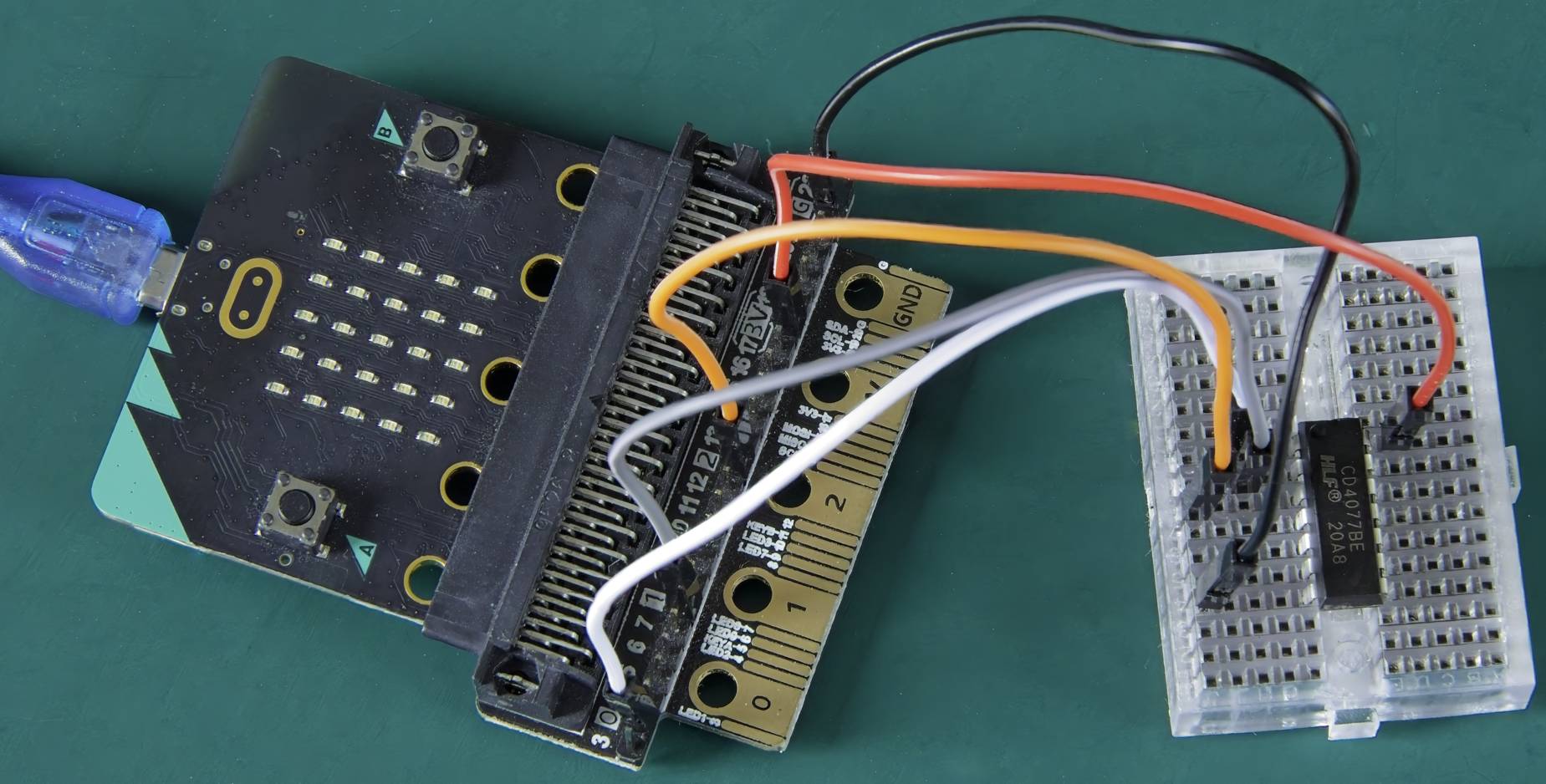
The following example tests the first logic gate on the CD4077BE IC. The CD4077BE is a quad 2-Input XNOR gate chip. The datasheet for this chip is easily found online and the pinout should always be checked before proceeding.
Connect the micro:bit to one of the logic gates on the CD4077BE using the connections given in the above tables.

Example
# Tests a 2-input logic gate.
# Returns the Truth Table and the
# Logic Gate type in a formatted report.

'''
microbit  Logic Gate
   pin0     Input 1
   pin1     Input 2
   pin2     Output
'''
from fc_2input_logic_gate_tester import *
lgt = LGT()
lgt.Report()

Output:
TRUTH TABLE
In1 In2 Out
 0   0   1
 0   1   0
 1   0   0
 1   1   1

Logic Gate: XNOR
Enjoy!
Testing 2-Input Logic Gate IC's
Download as zip file
'''
Tester for 2-input logic gates.
Identify/test the following gate types:
AND, NAND, OR
NOR, XOR, XNOR

AUTHOR  : fredscave.com
DATE    : 2024/10
VERSION : 1.00
'''

from microbit import *

LG_Dict = {'AND':'0001', 'NAND':'1110',
           'OR':'0111', 'NOR':'1000',
           'XOR':'0110', 'XNOR':'1001'}

class LGT():
    def __init__(self, PINin1 = pin0,
                       PINin2 = pin1,
                       PINout = pin2):
        self.PINin1 = PINin1
        self.PINin2 = PINin2
        self.PINout = PINout

    @staticmethod
    def get_key(value):
        # Given a value, find the first
        # matching key in the dictionary.
        for key in LG_Dict:
            if LG_Dict[key] == value:
                return key
        return None

    def GetTruthTable(self):
        # Returns a truth table as
        # a list of lists.
        truth = list()
        for i1 in range(2):
            for i2 in range(2):
                self.PINin1.write_digital(i1)
                self.PINin2.write_digital(i2)
                out = self.PINout.read_digital()
                l = [i1, i2, out]
                truth.append(l)
        return truth

    def PrintTruthTable(self):
        # Get the raw truth table
        truth = self.GetTruthTable()
        print('TRUTH TABLE')
        print('In1', 'In2', 'Out')
        # print each line of truth table
        for x in range(4):
            print(' ', truth[x][0], '   ', truth[x][1],
                  '   ', truth[x][2], sep='')


    def LogicGate(self):
        # This method gets the truth table
        # then builds a string of all the outputs.
        # The string is checked against a dictionary
        # of outputs for all gate types. If a
        # match is found that is returned as
        # logic gate type.
        truth = self.GetTruthTable()
        output = ''
        for x in range(4):
            output += str((truth[x][2]))
        Gate = LGT.get_key(output)
        if Gate != None:
            return Gate
        else:
            return 'Unknown gate'

    def Report(self):
        # prints a formatted report of the truth table
        # and the logic gate type found.
        print('\n')
        self.PrintTruthTable()
        print('\nLogic Gate:', self.LogicGate(), '\n')