AHT10, AHT15 Humidity & Temperature Sensors
Contents
AHT1X Family Description
The ASAIR AHT10 and AHT15 are entry level humidity and temperature sensors from the Chinese company, AOSONG Electronic Co. They are inexpensive and appear readily available (at time of writing, 2024) especially through Chinese online stores.
The AHT10 has been superseded by the AHT20. The AHT15 replacement is the AHT25.
The supply voltage for both chips is 1.8V to 3.6V. The AHT10 is often found on breakout boards which have an onboard voltage regulator and a logic level shifter to accommodate 5V microcontrollers such as some of the Arduino suite.
The claimed typical current draw for both of these sensors during measurement is a miserly 23 µA. Similar sensors from competitors have a measurement cycle typical current draw of 400 µA and sometimes much higher. So this very low figure quoted probably represents an average current usage during a sampling period e.g. 1 measurement taken every two seconds.
Sensor Type and AccuracyRelative humidity is measured with a capacitive humidity sensor. This sensor consists of a hygroscopic dielectric material placed between a pair of electrodes that forms a small capacitor. The measured capacitance of the device changes as the dielectric material absorbs or loses moisture in proportion to the relative humidity of the surrounding air.
Temperature is most likely measured with a bandgap temperature sensor, though not explicitly stated in the datasheet. This class of sensor relies upon the temperature dependent voltage characteristic of silicon diode e.g. base-emitter junction of a bipolar junction transistor. They are more accurate and with better resolution than other measurement systems such as RTDs and thermocouples but don't have the extreme temperature range capability.
The product datasheet gives the following typical accuracies for both sensors:
- Relative Humidity: ±2%.
- Temperature : ±0.3°C.
The maximum quoted accuracies are:
- Relative Humidity: ±3% between RH of 20% to 80%
- Temperature: ±0.4°C between temperatures of 15°C to 55°C
It is claimed that each sensor at time of manufacture is “rigorously calibrated and tested”.
Sensor PackagingIt is probable that the only essential difference between the AHT10 and AHT15 sensors is in their packaging.
The AHT10 is available in a two-sided, leadless flat SMD (Surface Mount Device) package. The body is 4.0mm x 5.0mm and has a height of 1.6mm.
The AHT15 is very different, being of a modular design. It has a body with similar dimensions to the AHT10 but with a flat tongue that extends out into a broader flat surface with four protruding pins. These pins will plug into a 4-contact DF13 socket. The idea is that they are easy to replace as a pull-out/ plug-in component in an appliance.
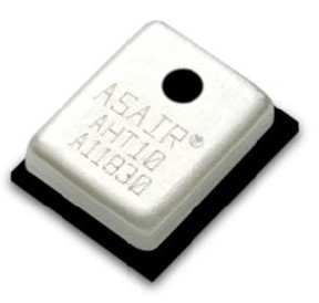
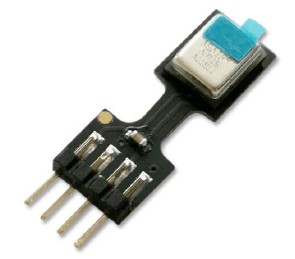
Fig 1 - [L to R] AHT10 chip and AHT15 module (at different scale)
Each chip is laser etched with the sensor type and its manufacturing batch number. Neither chip has a programmatically available serial or ID number burnt into static memory.
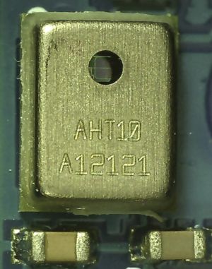
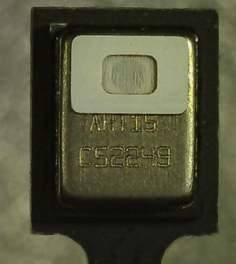
Fig 2 - [L to R] Micrographs of (1) AHT10 chip and (2) AHT15 chip.
The AHT10 package has a circular hole on its top surface that exposes the sensor directly to the atmosphere.
The AHT15 has the same circular hole on the top of its package, allowing the sensor to equilibrate to atmospheric conditions. However it is protected by a waterproof and dustproof PTFE membrane. This is clearly shown in Fig 2.
Microcontroller Connection Options
Neither sensor comes in a breadboard friendly package. However that problem is easily rectified especially in the case of the AHT10. These are very simple sensors and great for the hobbyist to learn about.
AHT10
The AHT10 is readily available on inexpensive breakout boards.
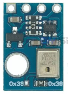
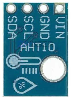
Fig 3 - Both sides of the AHT10 breakout board
In addition to the sensor chip the board also contains:
- 662K 3.3V regulator so is suitable for 5V (e.g. Arduino) use.
- Decoupling capacitors for power stability
- Logic level shifter so the board's I2C pins are 5V tolerant.
- Pullup resistors (10kΩ) for the I2C pins.
As can be seen in Fig 3 the pinout for the breakout board is simple and well labelled:
- VIN : power supply; 3.3V and 5V are fine.
- GND : Ground.
- SCL : I2C serial clock, pin19 on the micro:bit
- SDA : I2C bidirectional serial data pin20 on the micro:bit.
AHT15
The AHT15 sensor is provided in a simple modular form by the manufacturer and is not available on breakout boards. The sensor will plug into a 4-pin DF13 connector. A DF13 to Dupont converter cable marketed as an "APM 2.5 I2C Interface Cable 20cm" can occasionally be found for sale on eBay - See Fig 4.
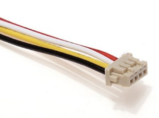
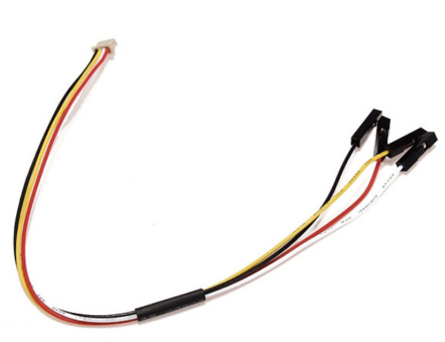
Fig 4 - [L to R] - (1) 4-wire DF13 connector, (2) APM 2.5 I2C Interface Cable 20cm
Alternatively, a 4-wire cable with DF13 connectors on each end (readily available) can be cut in half and two adapter cables made by soldering Dupont connectors onto the cut ends.
The AHT15 must be powered with a source 1.8V to 3.6V which makes this very suitable for the micro:bit. If 5V GPIO pins are to be used (e.g. Arduino) then a logic level converter will also be required.
Care must be taken that the sensor pins are correctly connected to the microcontroller pins. The pinout on this sensor is different to the breakout board of the AHT10. Fig 5 (from the product datasheet) shows the correct pinout.

Additionally, pullup resistors must be used on the two I2C pins. This isn't usually a problem as many microcontrollers have internal pullups on their digital GPIO pins. The micro:bit's pin19 and pin20 are fine for this purpose.
Accessing the AHT1X Sensors
The AHT1X sensors are quite basic and have only three user issuable commands (Initialisation, Measurement and Soft-reset) and a single read-only status byte.
Commands are written and the status byte is read via I2C. Both sensors come from the factory with an address of 0x38. This address is fixed for the AHT15 module. However it is reported on many online forums that the AHT10 address can be changed to 0x39.
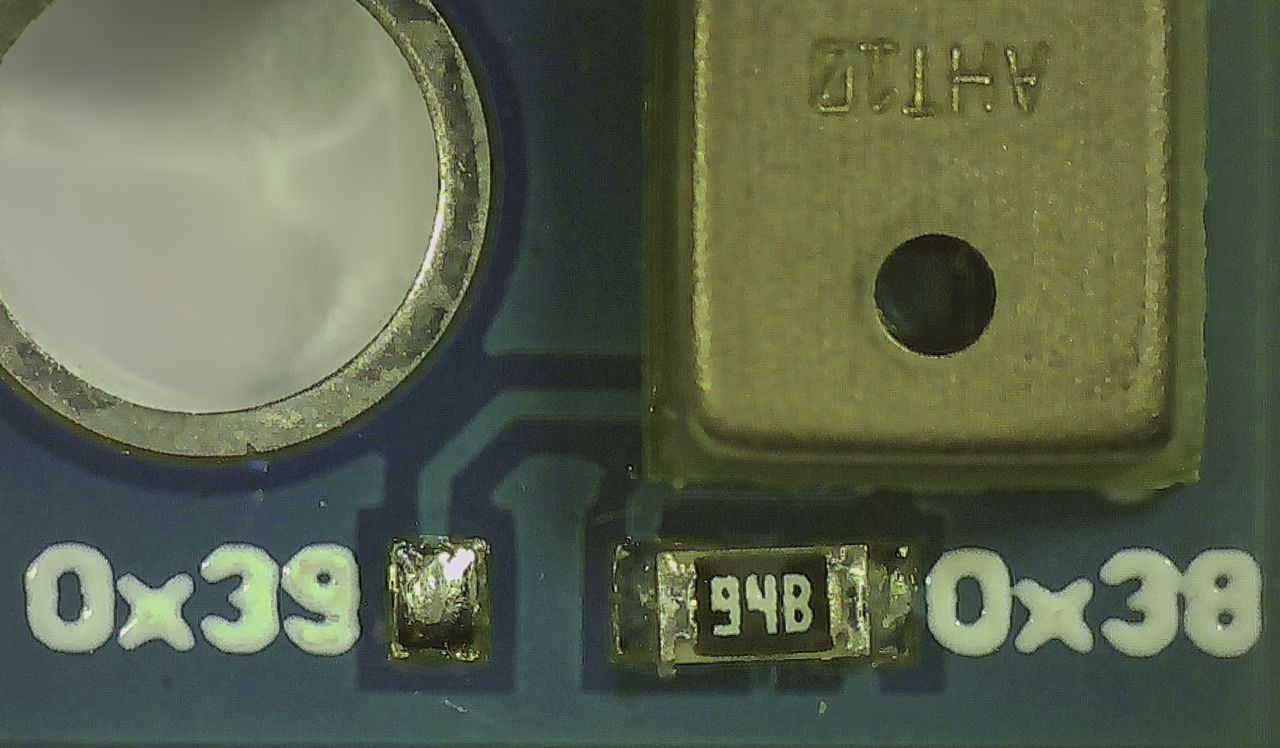
It is reported that the AHT10 I2C address can be changed from 0x38 to 0x39 if the 10kΩ resistor is unsoldered from the right-side tab then soldered onto the left-side tab.
I2C IssuesThe datasheet bizarrely states only a single AHT10 can be connected to the I2C bus and no other I2C devices can be connected
. The English version of the datasheet has been translated from the original Chinese and it has been suggested that this may be a translation error.
However, online forums report that there may be some truth to this. While other I2C devices may be connected to the same bus with these sensors it appears that the I2C bus may freeze after some time. It's therefore suggested that for mission critical projects that AHT20 or AHT25 sensor units be substituted for the AHT10 and AHT15.
Initialisation
The sensor should be sent an Initialisation command before the first measurement is requested. If the driver is implemented as a class then this can be done in the class constructor.
The Initialisation command consists of writing the command byte 0xE1 followed by two parameters 0x08 and 0x00.
Reading Humidity and Temperature
The Measurement command consists of writing the command byte 0xAC followed by two parameters 0x33 and 0x00.
The sensor takes more than 75ms to take the reading and process it. The status byte is polled until the Busy indication bit (Bit[7]) returns 0 meaning the device is idle.
Six bytes are read after issuing the Measurement command. The first byte is the status byte. The remaining five bytes (40-bits) contain the raw measurement value for relative humidity and temperature.
Of the 40-bit raw measurement result, the 20 MSB (most significant bits) is the relative humidity value. The 20 LSB (least significant bits) contains the temperature value. The raw values are converted to RH% and °C via formulae given in the datasheet.
Soft Reset
A soft reset can be performed on the sensor chip by writing the Soft-reset command 0xBA with no additional parameters. The reset restores default settings and is completed in less than 20ms. There is no return value to be read after the reset has completed.
MicroPython Driver for micro:bit
An AHT1x sensor family MicroPython driver specifically for the micro:bit has been developed as part of this series on MicroPython for the microbit. The driver webpage also provides a detailed description of the driver's methods with sample code.
The driver allows a user to easily connect and control these sensors from a micro:bit.
The AHT1x driver is implemented as a class. It's easy for a knowledgeable user to extend the class.
The AHT1x driver implements the full function set of this chip family. Included are methods that allow the user to:
- Initialise the sensor.
- Read the relative humidity and temperature.
- Perform a soft reset of the sensor.