AHT30 Humidity & Temperature Sensor
Contents
AHT30 Description
The ASAIR AHT30 is a third generation humidity and temperature sensor from the Chinese company, AOSONG Electronic Co. It is inexpensive and is readily available (at time of writing, 2024) especially through Chinese online stores.
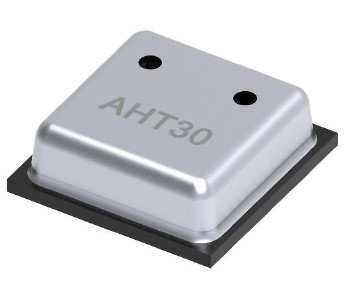
The supply voltage for both chips is 2.2V to 5.5V.
The claimed typical current draw for the AHT30 sensor during measurement is 570 µA. This is fairly typical for this type of sensor.
Sensor Type and AccuracyRelative humidity is measured with a capacitive humidity sensor. This sensor consists of a hygroscopic dielectric material placed between a pair of electrodes that forms a small capacitor. The measured capacitance of the device changes as the dielectric material absorbs or loses moisture in proportion to the relative humidity of the surrounding air.
Temperature is most likely measured with a bandgap temperature sensor, though not explicitly stated in the datasheet. This class of sensor relies upon the temperature dependent voltage characteristic of silicon diode e.g. base-emitter junction of a bipolar junction transistor. They are more accurate and with better resolution than other measurement systems such as RTDs and thermocouples but don't have the extreme temperature range capability.
The product datasheet gives the following typical accuracies for both sensors:
- Relative Humidity: ±3%.
- Temperature : ±0.5°C.
On these numbers this sensor is being reported as less accurate than the second generation AHT20 (±2% and ±0.3°C respectively) Maybe the accuracy of the AHT20 was slightly overstated. Regardless, these are fairly typical values for sensors using these technologies.
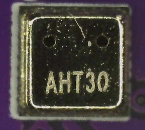
Sensor PackagingThe AHT30 has an identical footprint to that of the AHT20 chip. The only obvious external difference is in the shape and number of atmospheric exposure holes on the top surface of the sensor packages. The AHT20 has a single rectangular shaped hole while the AHT30 has two small circular vents each with a radius of 0.3mm.
The sensors are available as a two-sided, leadless flat SMD (Surface Mount Device) package.
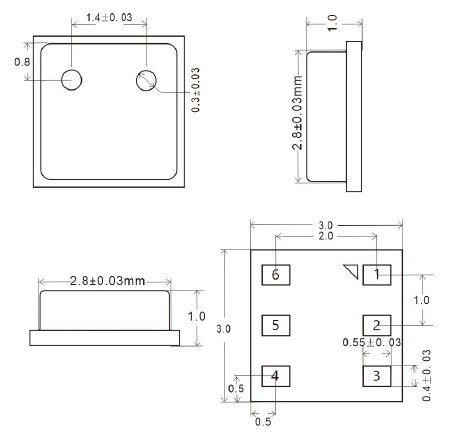
The AHT30 chip measures 3mm x 3mm and sits on a tiny platform giving a total height of 1mm. As shown in the micrograph of the chip below, the two sensor holes in the top of the packaging are circular shaped.
Microcontroller Connection Options
This sensor come in a tiny SMD package that is not breadboard friendly. However that problem is easily rectified with readily available and inexpensive breakout boards. This is a very simple sensor and easy for the hobbyist to learn about when purchased as a breakout board.
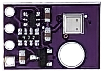
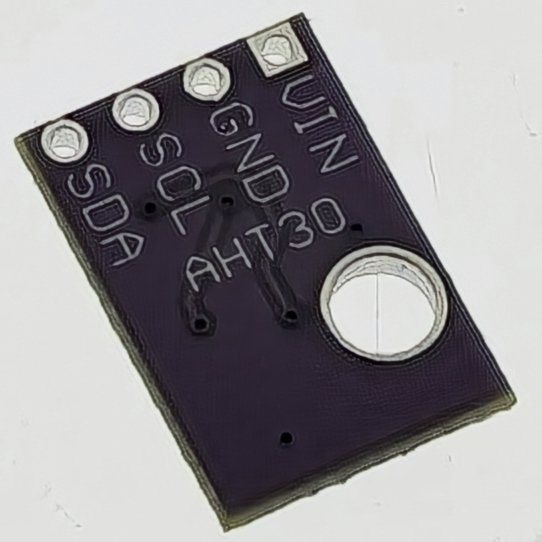
Fig 4 - Both sides of a popular AHT30 breakout board
In addition to the sensor chip the board also contains:
- 662K 3.3V regulator.
- Decoupling capacitors for power stability.
- Logic level shifter.
- Pullup resistors (10kΩ) for the I2C pins.
Strictly speaking the voltage regulator and logic level shifter aren't required as the chip will work with a 5V power supply. The board design is identical to a popular AHT10 breakout board but with the sensor swapped out for the AHT30.
As can be seen in Fig 4 the pinout for the breakout board is simple and well labelled:
- VIN : power supply; 3.3V and 5V are fine.
- GND : Ground.
- SCL : I2C serial clock, pin19 on the micro:bit
- SDA : I2C bidirectional serial data pin20 on the micro:bit.
Accessing the AHT30 Sensor
The AHT30 datasheet provides much less details with respect to the commands that the user can issue to the sensor than the earlier AHT1x and AHT2x sensors. There is only a single documented command, Measurement, and a table explaining most of the bits in the Status byte.
The Measurement command is written and the status byte is read via I2C. Both sensors come from the factory with a fixed address of 0x38.
Calibrated State of the Sensor
The chip runs a calibration routine during power-on. The success of the calibration process can be obtained by reading the Status byte. If Bit[3] of the Status byte is 1 then the chip has successfully calibrated itself at power-on.
If calibration is unsuccessful then this may be as a result of OTP memory corruption. Calibration constants are burnt to the static OTP memory during manufacture. A problem with the OTP memory can be detected by examining Bit[4] of the Status byte where a value of 0 indicates a memory fault.
If there is an issue with the calibration state the sensor will still measure and return humidity and temperature data. It just won't have been corrected for accuracy drift detected during testing before leaving the factory.
Reading Humidity and Temperature
The Measurement command consists of writing the command byte 0xAC followed by two parameters 0x33 and 0x00.
The datasheet advises to wait 80ms for the sensor to take the reading and process it. The status byte can be polled until the Busy indication bit (Bit[7]) returns 0 meaning the device is idle.
Seven bytes are read after issuing the Measurement command. The bytes in read order are:
- Byte 1 : Status byte
- Bytes 2 to 6: Raw humidity and raw temperature data
- First 20 bits : Raw humidity data
- Second 20 bits : Raw temperature data
- Byte 7 - Checksum calculated over the five data bytes
The raw values are converted to RH% and °C via formulae given in the datasheet.
The user can calculate a checksum across the 5-bytes of data read, then compare it with the checksum received from the sensor. The humidity and temperature reading can be accepted with high confidence If the checksums are equal.
Details of the checksum algorithm are provided in the datasheet and there is sample C++ code on the manufacturer's website.
MicroPython Driver for micro:bit
An AHT30 MicroPython driver specifically written for the micro:bit has been developed as part of this MicroPython for the microbit series. The driver webpage also provides a detailed description of the driver's methods with sample code.
The driver allows a user to easily connect and control these sensors from a micro:bit.
The AHT30 driver is implemented as a class. It's easy for a knowledgeable user to extend the class.
The AHT30 driver implements the meager functionality in full as described by the product datasheet. Included are methods that allow the user to:
- Return the Status byte from the sensor.
- Check the sensor's calibration status.
- Interpret all the documented bits of the Status byte.
- Read the relative humidity and temperature.
- Return data confidence by comparing the checksums.