UART Introduction for micro:bit
Contents
Introduction to UART
This blog introduces the basis of how data flows between two UARTS. The uart object and its methods - from MicroPython's microbit module - are examined in some detail. Finally the 'pros' and 'cons' of the UART are listed.
The next webpage in this series ties this all together with a project that uses the micro:bit's UART in a MicroPython program to send bytes to a terminal program running on a computer.
UART - Universal Asynchronous Receiver-Transmitter - is not (strictly speaking) a protocol. It is hardware[1] (a chip or a circuit) on an electronic device (computer, sensor, display, etc) that uses an asynchronous serial transmission protocol to communicate with the UART on another device.
The transmitting UART takes parallel data (e.g. from a bus), converts it to a serial data stream and transmits it bit-by-bit to the receiving UART. The receiving UART converts it back to the form as the original parallel data.
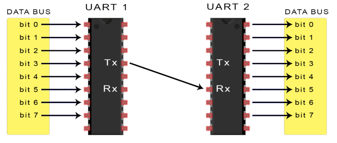
Note from FIG 1 that each UART has two wires used for data transfer - transmit (Tx) and receive (Rx). It is important that these wires are crossed i.e. the Tx line on one UART must be connected to the Rx line on the other UART and vise versa.
Failure to cross-wire the Tx and Rx pins is a common reason why a hobbyist's UART project fails on first attempts.
Serial Data Transmission
UART uses an asynchronous serial transmission protocol. This means that bits are sent one after the other without a shared clock signal. Each UART is responsible for its own timing while sampling the data line.
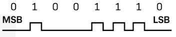
Electrically bits are usually represented as voltage differences with a 0 being a low voltage (e.g. 0V) and a 1 represented by a high voltage (e.g. 3.3V). With a rapid transition between the two voltage levels the resultant data signal is in a square wave form.
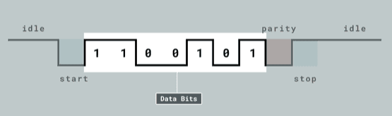
A UART transmission consists of a single UART frame that is made up of the following in the given order:
- A single start bit
- The data character
- An (optional) parity bit
- One or more stop bits
Baud rate
Baud rate refers to the speed of the data transmission and is expressed as bits per second abbreviated to bps Since the transmitter and the receiver must use their own clocks (i.e. there is no shared clock pulse) it is essential that the baud rate is agreed before data transmission begin.
Historically, common baud rates include 9600, 19200, 38400, and 115200 bps. The micro:bit's REPL operates at 115200 bps.
Start bit
The single start bit sent by the transmitter is to alert the receiver that a frame is about to be transmitted. The start bit is always a logical LOW.
Data character
The number of bits composing the data character is agreed between the two UARTs before data transfer can take place. It is usually in the the range of 6 to 8 bits with 8 bits being the most common. This allows for the transmission of a conventional byte and represents 256 different possible values.
The meaning (encoding) of the data bits must also be commonly understood between the transmitter and receiver. They could represent ASCII characters, numerical values, etc.
Parity bit
The parity bit, which is optional, is used as a data integrity check. The parity can be either even parity or odd parity. If it is agreed between the transmitter and receiver that a parity bit will be sent then they must also agree whether it will be even parity or odd parity.
The number of bits of the data character with a value of 1 are counted and the parity bit is set according to which type of parity (even or odd) has been specified.
| Parity | # of 1's | Parity bit |
|---|---|---|
| even | even | 0 |
| even | odd | 1 |
| odd | odd | 0 |
| odd | even | 1 |
... and best explained with an example:
| Data character | 1 0 0 1 1 0 1 |
| ...with even parity | 1 0 0 1 1 0 1 0 |
| ...with odd parity | 1 0 0 1 1 0 1 1 |
Stop bit
The end of the transmission is signalled by raising the transmit line HIGH for at least the duration of two bits.
The micro:bit uart Object
The micro:bit's UART is easy to use. There are two things to remember though:
- When physically wiring between the microbit's UART pins and the pins of the other device remember to cross-cable the Tx and Rx pins on each device.
The MicroPython REPL (console) uses the micro:bit's UART and will become unavailable when a program initialises the UART for its own use.
NOTE: If the program using the UART terminates with an error the REPL may still be unavailable but this does not prevent programs being flashed to the micro:bit i.e. the micro:bit is not 'bricked'!
The microbit module provides the uart object that exposes methods for (1) initialising, (2) reading and(3) writing to the UART.
Initialising the UART
The uart object provides the init() method for initialising the micro:bit's UART; a necessary step before any serial transmission can occur.
Syntax:
uart.init(baudrate, bits, parity, stop, tx, rx)

Where:
  baudrate : Baudrate in bits per second.
             Default = 9600

  bits : Number of data bits. Default = 8
         This parameter can be ignored
         because it can't be changed from
         its default value.

  parity : One of uart.ODD, uart.EVEN, None
           Default = None

  stop : Number of stop bits. Default = 1
         This parameter can be ignored
         because it can't be changed from
         its default value.

  tx : Transmit pin, Default = None
  rx : Receive pin, Default = None
       These can be assigned to any
       available digital pins.
       NOTE: tx and rx are mandatory
       keyword arguments.

Example:
from microbit import *

# baud 9600, 8 bits data, no parity
uart.init(tx=pin0, rx=pin1)

# baud 14400, 8 bits data, even parity
uart.init(14400, 8, uart.EVEN, tx=pin0, rx=pin1 )

# This will cause an error because
# tx and rx must be keyword arguments
uart.init(9600, 8, None, 1, pin0, pin1)
NOTE: Any program that uses the uart object should make the call uart.init(115200) before the program terminates so that the MicroPython REPL is restored.
Reading from the UART
The uart object provides the following methods that allows the micro:bit's UART to request data from the external UART:
| Method | Description |
|---|---|
| uart.any() | Returns True if there is data waiting to be read. |
| uart.read([nbytes]) | If nbytes is specified then that many bytes is read, otherwise read as many bytes as available. Return value: a bytes object. |
| uart.readinto(buf [, nbytes]) | Reads bytes into buf. If nbytes is specified then read that many bytes otherwise read at most len(buf) bytes. buf : usually a bytearray object. |
| uart.readline() | Reads a line, ending in a newline character '\n'. The newline character is also returned. Return value: a bytes object. |
If there is no valid data to read then read(), readinto() and readline() will return the value None.
Writing to the UART
The uart object provides the write() method to transmit data to the external UART.
Syntax:
uart.write(buf)

Where:
  buf : Data to be written by the micro:bit's UART.
        It can be a string or a bytes object.

Example:
from microbit import *
uart.init(tx=pin0, rx=pin1)
uart.write('Test String')
uart.write(b'Another test string')
uart.init(115200)
print('The REPL is back!')
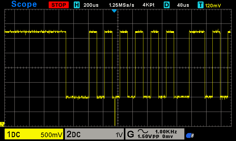
The above example program is fine to flash to the micro:bit. It will not raise an exception (error) if no pins are connected to an external UART. However it is possible to capture the signal on an oscilloscope. Fig 5 shows part of the UART output from the above program.
UART Pros & Cons
[4]Advantages include:
- Only uses two wires
- No clock signal wire is needed
- Has an (optional) parity bit to allow for error checking
- The structure of the data packet can be changed as long as both sides are set up for it
- Well documented and widely used method
[4]Disadvantages include:
- The size of the data frame is limited to a maximum of 9 bits
- Doesn't support multiple slave or multiple master systems
- The baud rates of each UART must be within 10% of each other
- Slow compared to synchronous protocols