Using SPI with the micro:bit
Contents
Introduction
This page is part of a series on using MicroPython with the BBC micro:bit. Specifically, Serial Peripheral Interface (SPI) is explained in brief (not too technical terms!) with emphasis on how to use it on the micro:bit with MicroPython.
A simple project interfaces the micro:bit with a 7-segment, 8-digit LED display containing a MAX7219 controller chip. The MAX7219 controller, with its very easy to use SPI interface, is programmed by the micro:bit to turn on test mode which lights up all the segments on the LED display.
A second project interfaces the micro:bit with a BMP280 barometric pressure sensor module. The BMP280 sensor chip has an id value burnt into an onboard register. The ease of using the SPI serial protocol on the micro:bit is demonstrated by reading this id value from the sensor.
SPI Explained
Introduction
Serial Peripheral Interface (SPI and pronounced S-P-I) is a simple to use serial protocol. It is synchronous with just a single clock used to co‑ordinate data transmission. With the use of a single clock there is no need for start and stop bits.
SPI 4-Wire
Data is transferred in both directions between a master and slave combination. SPI is a 4-wire protocol.
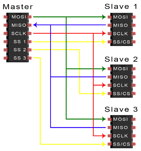
There is only one master allowed but this master may control many slaves. Each slave has one unique wire connection (Chip Select) to the master but shares the other three wires with all other slaves.
The four wires used by the SPI protocol:
- MOSI (Master Out/Slave In) - line for transferring data from master to slave.
- MISO (Master In/Slave Out) - line for transferring data from slave to master.
- SCLK (Clock) - provides a single clock source between the master and all attached slave.
- CS (Chip Select) - used to signal the slave that communications are about to occur. A unique CS line is required between each slave with its master.
SPI does not have a written standard so these wire names are not set in stone and may be referred to by slightly different names in product datasheets. Regardless, the functionality is the same.
SPI Data Transfer
FIG 1 shows the simple connection of the master connected with only one slave. The CS line is held HIGH in the idle condition. Communications is initiated between the master and the slave when the master pulls the CS line LOW.
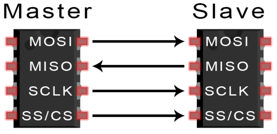
The master is responsible for the clock signal. During each clock signal a single bit is sent from the master to the slave on the MOSI line or from the slave to the master on the MISO line.
After all data has been transferred, the master pulls the CS line HIGH again.
Master and Multiple Slaves
It is simple to add multiple slaves to the setup. As stated above each slave has its own master-slave CS line but shares the SCLK, MOSI and MISO lines.
SPI Modes
Apart from correctly identifying the four SPI pins on the slave there is only one other piece of information required before programming the SPI interface between the two device. Its referred to as the SPI mode.
The mode describes whether:
- The clock is HIGH or LOW when at idle
- The data bit is sampled on the leading edge or the trailing edge of the clock.
Most product datasheets explain their SPI implementation with a timing diagram such as that shown in FIG 3 for the BOSCH BMP280 digital pressure sensor.
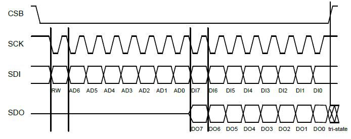
It is possible to deduce the SPI mode from these timing diagrams. However this is usually unnecessary as most datasheets will also explicitly state which SPI mode is being used. Take as an example the datasheet[2] for the BOSCH BMP280 digital pressure sensor:
“The SPI interface is compatible with SPI mode '00' (CPOL = CPHA = '0') [mode 0] and mode '11' (CPOL = CPHA = '1') [mode 3].
The automatic selection between mode '00' and '11' is determined by the value of SCk [SCLK] after the CSB [CS] falling edge.“
This is somewhat long winded but is simply stating that mode 0 or mode 3 can be used with this sensor. This is no surprise since most SPI slaves will work by default with mode 0.
References
Using SPI on the micro:bit
The spi object from the microbit module makes it incredibly easy to use SPI with MicroPython on the micro:bit. The spi object supports the following methods:
- spi.init() - initialises SPI on the micrco:bit.
- spi.write() - micro:bit writes data to the slave
- spi.read() - micro:bit reads data from the slave.
- spi.write_readinto() - micro:bit writes data to the slave and simultaneously reads data back from the slave.
Initialising SPI
Syntax:
spi.init(baudrate, bits, mode, sclk, mosi, miso)

Where:
  baudrate : Defines the speed of transmission
             in bits per second. This does not
             need to be agreed between master
             and slave as the master operates
             the clock. Any baud rate that the
             slave is able to respond to will
             be fine.
             Default = 1000000

  bits : Defines the size of bytes being
         transmitted. Currently only 8 bits
         is supported.

  mode : SPI mode that must be used for the
         slave to correctly respond to the SPI
         protocol. Most devices support mode=0
         but read the datasheet for confirmation.
         Default = 0

  sclk : Pin used on the micro:bit for
         the clock. It is advisable to
         use the default pin.
         Default = pin13

  mosi : Pin used on the micro:bit for
         transfer of data from master
         to slave. It is advisable to
         use the default pin.
         Default = pin15

  miso : Pin used on the micro:bit for
         transfer of data from slave
         to master. It is advisable to
         use the default pin.
         Default = pin14

NOTE: Unless there is compelling reason
      otherwise it is best (and simpler!)
      to just use the defaults.

Example:
# Using the defaults
from microbit import spi
spi.init()
Master Writes to Slave
Syntax:
spi.write(buffer)

Where:
  buffer : Data bytes that are written out by
           the master. The buffer must be
           an object with buffer protocol.

           Usually this will be a bytes object,
           byte array, urray object or string.
           It is common to use a bytes object.

Example:
from microbit import *
CMD = b'\x01'
# Initialise SPI
spi.init()
# Start SPI transmission
pin0.write_digital(0)
# Write command to slave
spi.write(CMD)
# End SPI transmission
pin0.write_digital(1)
Master Reads from Slave
Syntax:
spi.read(nbytes)

Where:
  nbytes : The number of bytes (at most)
           to be read from the slave.

Returned : byte object with all the bytes
           received from the slave.

Example:
from microbit import *
# Initialise SPI on the micro:bit
spi.init()
# Start SPI transmission
pin0.write_digital(0) #CS pin
# Read at most 3 bytes from slave
buffer = spi.read(3)
# End SPI transmission
pin0.write_digital(1) #CS pin
print('Example output:', buffer)

Example output: b'\x05\x00\x02'
Note that the example output above is a bytes object containing 3 x 8-bit bytes.
Simultaneous Read & Write
The spi.write_readinto() method has the master write one or more bytes to the slave while the slave simultaneously sends one or more bytes back to the master.
It is more usually the case that the master will send a command to the slave after which the slave is asked for a response. This requires the use of the spi.read() and spi.write() methods used in sequence.
Syntax:
spi.write_readinto(out, in)

Where:
  out : Buffer of byte(s) that is written
        to the slave.
  in :  Simultaneously, any response from the
        slave is written into this buffer.

Notes:
  (1) The buffers must be MicroPython buffer
      protocol and be of the same length.
  (2) The two buffers can be the same object.

Example:
from microbit import *

# Define the buffers
buffer_out = b'\x01'
buffer_in = bytearray(1)

# Initialise SPI.
spi.init()
# Start SPI transmission.
pin0.write_digital(0) #CS pin
# Send a byte to the slave
# while receiving a byte from the slave.
spi.write_readinto(buffer_out, buffer_in)
# End SPI transmission
pin0.write_digital(1) #CS pin
The example given above will run on the micro:bit without throwing an exception (error) even in the case no SPI slave is attached. This is the nature of SPI on the micro:bit.
If there is no slave attached the micro:bit will still write data out using the SPI protocol on the configured pins. Similarly, a read will return the buffer populated with zeroes (0's). This applies to all three read/write methods of the spi object.
SPI Examples for the micro:bit
This section presents two very simple but real examples of SPI communication between the micro:bit and a slave.
The first example uses SPI to communicate with the MAX7219 controller chip on a 7-segment LED display and activate the display's test mode.
The second example uses SPI[3] to query and return the chip ID of a BMP280 barometric pressure sensor.
(1) The 7-Segment LED Display & MAX 7219 Controller
Introducing the MAX7219
The 7-segment LED display has been around a long time. It is a convenient way to display numbers and are still commonly used e.g. on digital clock displays where the digits need to be clearly seen in low light situations but the brightness of the display needs to be easily controlled.
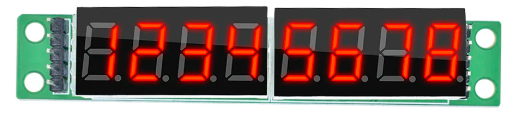
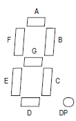
The 7-segment LED display consists of digits that each have seven LEDs arranged in a pattern of a robotic '8'. Lighting the correct combination of LEDs enables the displaying of all numbers between 0 and 9. FIG 4 above illustrates the concept.
Each of these LED segments must be individually controlled. So, in the case of the 8-digit display shown in FIG 4 this equates to 56 individual LED segments. This is getting beyond the capabilities of many lower-end microcontrollers.
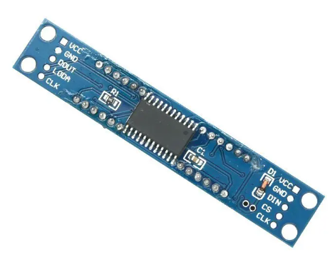
Instead, the task of doing this grunt work is usually farmed out to specialist display controller chips. One such chip is the MAX2719 which is commonly used to drive 7-segment LED displays.
The 7-segment 4-digit LED display with MAX7219 shown in FIG 4 can be purchased for less than US$1. These displays are robust, reliable and easy to use thanks to the onboard MAX2719 controller. This makes them a popular choice for many projects.
Conveniently the MAX7219 comes with an SPI interface making it easy to interface these displays with microcontroller platforms such as the micro:bit.
MAX7219 Test Mode
The MAX7219 provides a test mode that when activated lights up each LED segment of the display at near maximum brightness. The test mode is activated by writing a command value to the MAX2719 through the SPI interface.
The MAX7219 datasheet states that to turn on test mode the microcontroller writes a value of 0x01 to the test mode register 0x0F. Writing the value 0x00 to the same register resets the mode back to normal display.
This is done (very simply) by the microcontroller sending the two bytes as the bytes object b'\x0f\x01' through SPI to the MAX7219.
Component List
Hardware:
- 1 x BBC micro:bit V2
- 1 x 7-Segment 4-Digit LED Display with MAX7219
- 5 x Dupont F-F wires
Software:
- Mu Editor - or alternative MicroPython editor for the micro:bit
Wiring the Circuit
Since the communication between the master (micro:bit) and slave (MAX7219) is one way only there isn't any need for the MISO line (pin14).
Make the following connections:
| Step | micro:bit | Display |
|---|---|---|
| 1 | GND | GND |
| 2 | 3V | VCC |
| 3 | pin15 | DIN |
| 4 | pin0 | CS |
| 5 | pin13 | CLK |
The MicroPython Program
Connect the micro:bit to the computer to power it up. Copy the following program to the MicroPython editor and flash it to the micro:bit.
from microbit import *

LOW = 0
HIGH = 1
# MAX7219 test mode command.
# This writes 0x01 to register 0x0f.
TEST_MODE = b'\x0f\x01'

# Setup SPI with these defaults:
    # baudrate=1000000
    # bits=8
    # mode=0
    # sclk=pin13
    # mosi=pin15
spi.init()

# Start SPI transmission
pin0.write_digital(LOW) #CS pin
# Send command for test mode
spi.write(TEST_MODE)
# Latch data and end SPI transmission
pin0.write_digital(HIGH) #CS pin
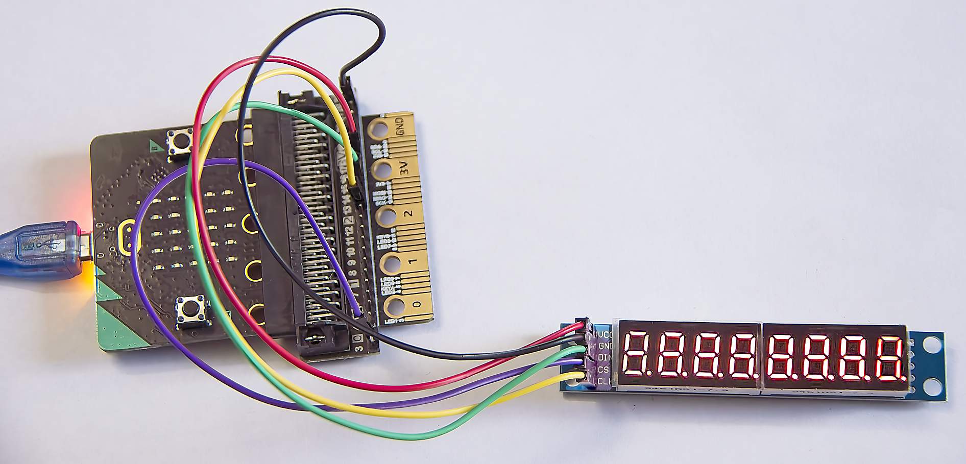
All LED segments of the display will light up. It will retain this state till the display is powered down.
(2) Reading the BMP280 Chip ID
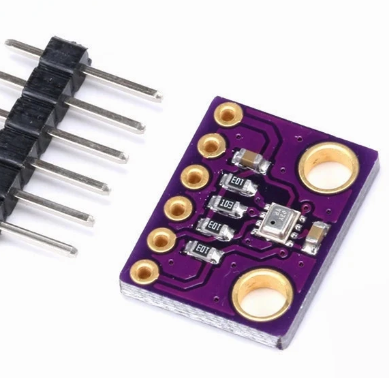
Introducing the BMP280 Sensor
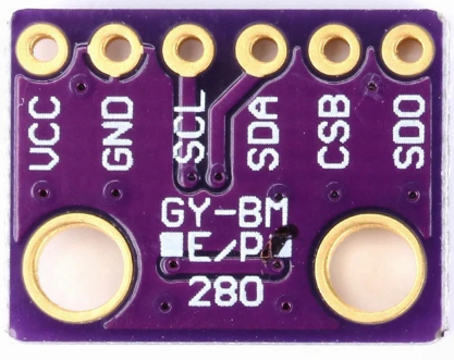
The BMP280 is an inexpensive barometric pressure sensor from BOSCH that is also capable of measuring ambient air temperature. It has both SPI and I2C serial interfaces. The hobbyist usually purchases this as a breakout board where it conveniently comes with pullup resistors on the serial pins.
BMP280 Chip ID
The BMP280 sensor chip has a read-only register that contains a chip id. This project will use SPI[3] to read this chip id.
This is an extract from the BOSCH BMP280 datasheet:
“4.3.1 Register 0xD0 'id'
The 'id' register contains the chip identification number chip_id[7:0], which is 0x58. This number can be read as soon as the device finished (sic) the power-on-reset.”
From this we learn that all BMP280 sensor chips have an id value stored as a read-only value in the on-chip register chip_id. Further on in the datasheet the address of this register is given as 0xD0.
The value in this register can be queried easily with the chip's SPI interface and (according to the datasheet) should always return 0x58.
Component List
Hardware:
- 1 x BBC micro:bit V2
- 1 x BMP280 module
- 6 x Dupont F-F wires
Software:
- Mu Editor - or alternative MicroPython editor for the micro:bit
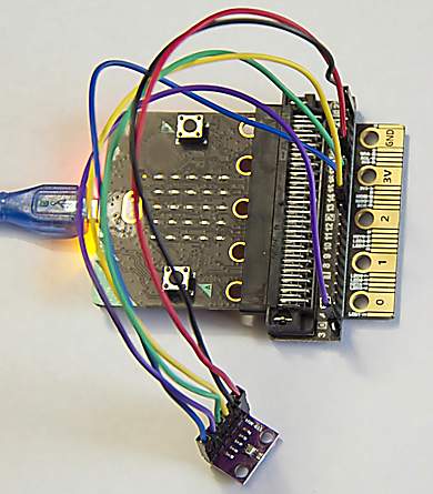
Wiring the Circuit
Make the following connections:
| Step | micro:bit | BMP280 |
|---|---|---|
| 1 | GND | GND |
| 2 | 3V | VCC |
| 3 | pin15 | SDA |
| 4 | pin0 | CSB |
| 5 | pin14 | SDO |
| 6 | pin13 | SCL |
The MicroPython Program
Connect the micro:bit to the computer to power it up. Copy the following program to the MicroPython editor and flash it to the micro:bit.
# Interrogates a BMP280 barometric
# pressure sensor for its ID.
# The correct ID will verify that
# the sensor chip is genuine.

from microbit import *

LOW = 0
HIGH = 1
ID_CMD = b'\xD0' #Register containing ID

# Initialise SPI on the micro:bit.
spi.init()
# Start SPI transmission.
pin0.write_digital(LOW) #CS pin
# Write command to slave for ID
spi.write(ID_CMD)
# Read 1 byte ID value from slave.
id = spi.read(1)
# End SPI transmission
pin0.write_digital(HIGH) #CS pin

# Format ID value to hex format
# then output it.
id = hex(ord(id))
print('ID Value:', id)
Click the REPL button to view the output:
Output:
ID Value: 0x58
Success! The id register on the BMP280 does indeed return the correct value of 0x58.
SPI Pros & Cons
Advantages include:
- High speed: It can operate at much higher speeds than I2C and especially UART.
- Simple to implement: It is point-to-point i.e. does not use an addressing mechanism such as required by I2C.
- Flexible: Can be used with multiple slaves.
- Low power consumption: Making it suitable for battery-powered devices.
- Highly Reliable: Uses a single clock between master and slave.
Disadvantages include:
- No written standard: No standards body has produced a standard so there is the risk that device manufacturers may make their own interpretations on the protocol.
- Limited distance: For components on the same PCB or very close by.
- Uses more microcontroller pins than other serial protocols: Requires the use of four pins for two-way communications between a single master-slave combination.