Using I2C with the micro:bit
Contents
Introduction
This page is part of a series on using MicroPython with the BBC micro:bit. Specifically, I2C (Inter-Integrated Circuit) is explained in brief (not too technical terms!) with emphasis on how to use it on the micro:bit with MicroPython.
A simple project interfaces the micro:bit with two barometric pressure sensors; BMP180 and BMP280. Both of these sensors are readily available. A MicroPython program on the micro:bit will perform an I2C scan that will detect these two sensors and report their I2C addresses.
A second project interfaces the micro:bit with the BMP280 barometric pressure sensor module. The BMP280 sensor chip has an id value burnt into an onboard register. The ease of using the I2C serial protocol on the micro:bit is demonstrated by reading this id value from the sensor.
I2C Explained
Phillips developed and added I2C to many of its devices from 1982. Pronounced "I-Squared-C" and often written as "I2C", it originally had a maximum speed of 100 kHz. The fast-mode option at 400 kHz was later introduced and around this time I2C became a formal written standard.
While it is much slower than other serial protocols such as USB, Bluetooth, WiFi and ethernet, I2C uses much less hardware and is considerably simpler to use. This makes it an excellent choice for peripherals targeted at microcontrollers.
A microcontroller is able to control multiple devices with just two GPIO digital pins (wires). One wire (SCL) is used to generate a clock signal while data is transmitted on the other wire (SDA).
Each peripheral attached to the microcontroller I2C bus must have a unique address. The address can be either 7-bits or 10-bits in length though 7-bit addresses are much more common for peripherals that a hobbyist will encounter.
The controller will always initiate the conversation with a peripheral so does not require an address.
Data is transferred in messages. Each message[1] is assembled as one or more frames of data.
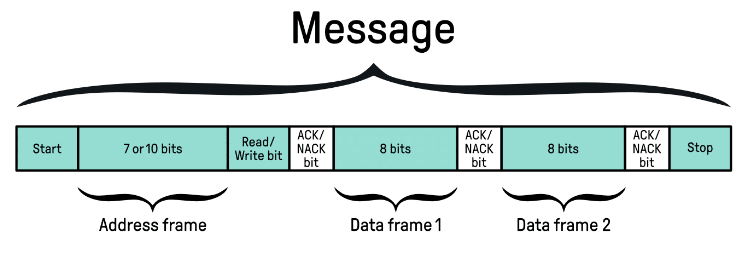
Start
The start condition is initiated by the controller holding the CLK (clock) line HIGH and pulling the SDA (data) line LOW. This alerts all peripherals on the bus.
Address frame
The controller transmit the 7-bit or 10-bit address frame. This initialises the conversation with the correct peripheral.
Read/Write bit
If the controller is to write data to the peripheral then it sends one LOW bit. A HIGH bit indicates that the peripheral will be sending data.
ACK/NACK bit
If the peripheral is ready, it will send an ACK bit by pulling the SDA line LOW for one bit. If there is an issue, the peripheral holds the SDA line HIGH for one bit.
Data frame(s) transmission
One or more data frames, each consisting of 8-bits (1 byte) will be sent by the controller if the write-bit was sent. If the read-bit was sent the peripheral will transmit data
An ACK or NACK bit is sent by the receiver after each 8-bits.
Stop
The stop condition indicating end of message is asserted by pulling both lines (SCL and SDA) to HIGH and holding them in this state.
Using I2C on the micro:bit
The microbit module provides the i2c object which makes I2C incredibly easy to use with micro:bit's MicroPython.
This i2c object handles all of the technical stuff - start/stop bits, read/write bit, ACK/NACK bits and clock signal.
The i2c object exposes the following four methods:
- i2c.init() - Initialises I2C between controller and peripheral.
- i2c.scan() - Perform a full scan of the I2C bus.
- i2c.write() - Controller writes byte(s) to the peripheral.
- i2c.read() - Controller reads byte(s) from the peripheral.
Initialising I2C
Syntax:
i2c.init(freq, sda, scl)

Where:
  freq : Clock frequency in Hz.
         Default : 100000

  sda : Pin to use for the SDA (data) line.
        Default : pin20

  scl : Pin to use for the SCL (clock) line.
        Default : pin19

NOTE: Unless there is a compelling reason to
      change these defaults it is best
      (and easiest) to just follow the status quo.

Example:
# Initialising I2C with the defaults
from microbit import i2c, pin19, pin20
i2c.init()
I2C Bus Scan
Syntax:
i2c.scan()

Notes:
This method performs a 7-bit address scan of
the full address range of the I2C bus.
It returns a MicroPython list of integers of
all addresses found active on the bus.

Example:
# BMP180 and BMP280 on I2C bus.
from microbit import i2c, pin19, pin20
i2c.init()
AddrList = i2c.scan()
print(AddrList)

  ⇒ [118, 119]
Controller writes to I2C bus
Syntax:
i2c.write(addr, buf, repeat)

Where:
  addr : peripheral 7-bit address (required)

  buf : Buffer protocol object (usually a
        string or bytes object) with the
        data to be written to the peripheral.

  repeat : No stop bit sent if repeat=True.
           Default : False

Example:
from microbit import i2c, pin19, pin20
Addr = 0x76
Cmd = b'\x01\x03'
i2c.init()
i2c.write(Addr, Cmd)
Controller reads from I2C bus
Syntax:
ic2.read(addr, n, repeat)

Where:
  addr : peripheral 7-bit address (required)

  n : Number of bytes to read from the
      peripheral (required).

  repeat : No stop bit sent if repeat=True.
           Default : False

Returns: Buffer protocol object (usually a
         bytes object) containing the number
         of bytes requested.

Example:
from microbit import i2c, pin19, pin20
Addr = 0x76
i2c.init()
# Read 5 bytes
data = i2c.read(Addr, 5)
I2C Example for the micro:bit
This section presents two very simple but real examples of I2C communication between the micro:bit and one or more sensors.
In the first example, two I2C capable sensors are interfaced with the micro:bit. The I2C bus is scanned and the number of devices discovered and their addresses are reported.
The second example uses I2C to query[2] and return the chip ID of a BMP280 barometric pressure sensor. This is also possible with the serial SPI protocol.
(1) Scanning for I2C Devices
The spi.scan() method from the microbit module makes it very simple to scan and discover devices on the micro:bit's I2C bus. This project will interface two common and inexpensive barometric pressure sensor modules to the micro:bit's I2C bus and use the scan() method to find them and report their addresses.
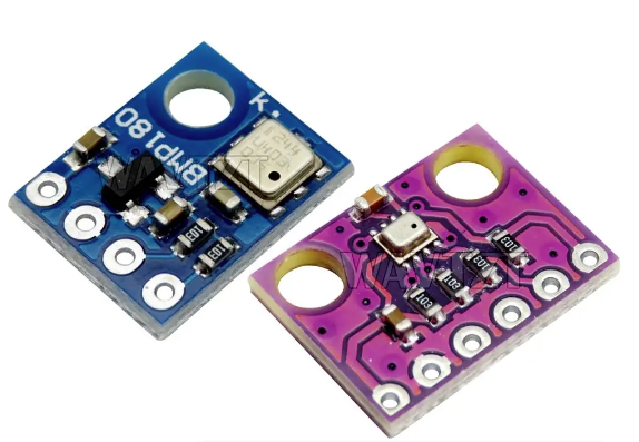
The BMP180 is a basic barometric pressure sensor that's also capable of measuring temperature.It communicates the results of its measurements through its I2C interface. With its very simple capabilities it's easy to write drivers that support this sensor on the common microcontroller platforms and hence is a popular hobbyist's choice for beginner-level projects.
The BMP280 is a newer and more advanced version of the BMP180 with a much richer feature set. It has both I2C and SPI interfaces. Both sensors can be found on breakout boards for less than US$1.
Component List
Hardware:
- 1 x BBC micro:bit V2
- 1 x BMP180 barometric pressure sensor module
- 1 x BMP280 barometric pressure sensor module
- 1 x breadboard
- 12 x Dupont F-M wires
Software:
- Mu Editor - or alternative MicroPython editor for the micro:bit
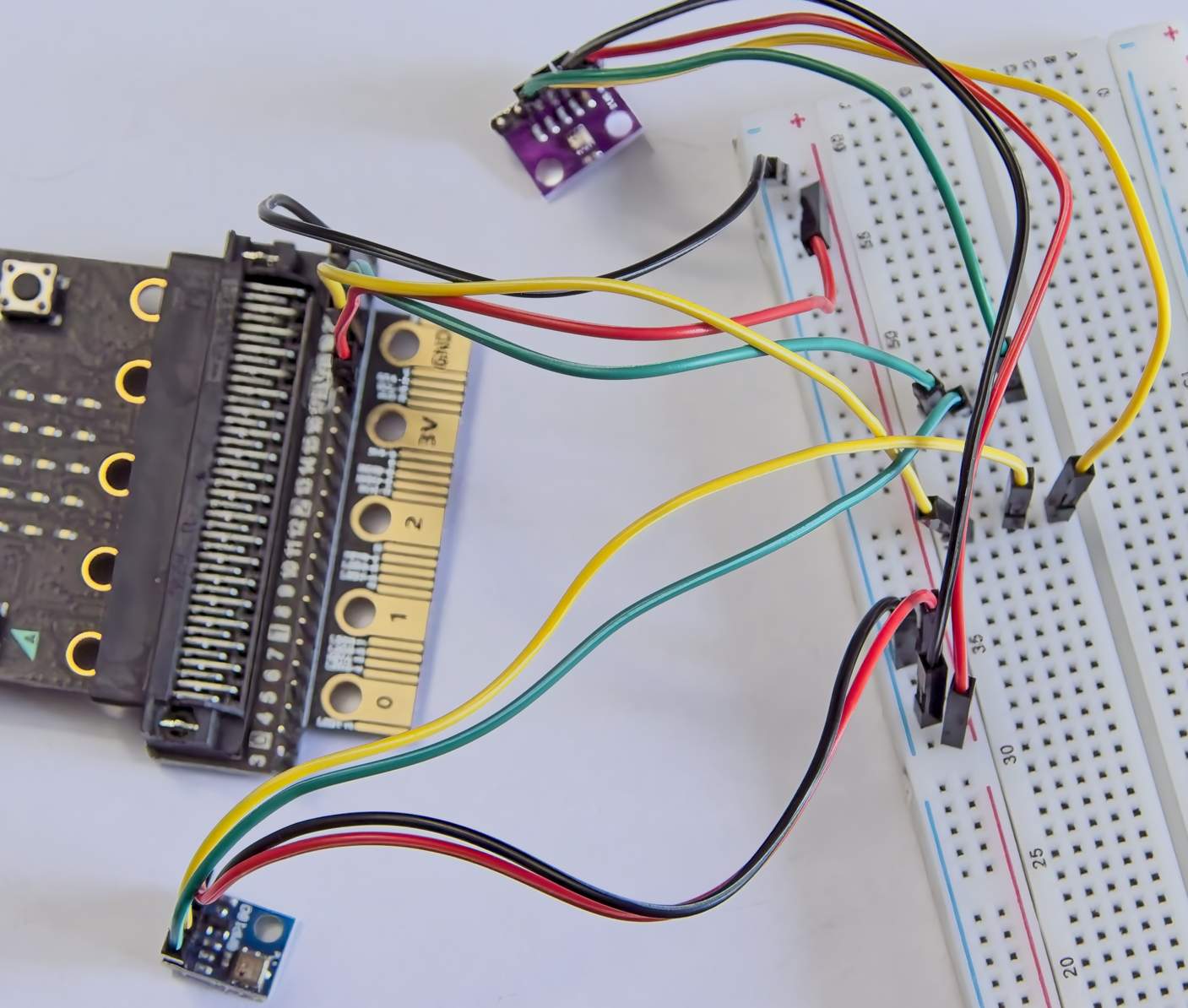
Wiring the Circuit
While there's quite a lot of wires, its really quite simple.
While the micro:bit is powered down make the following connections:
| Step | micro:bit | BMP180/280 |
|---|---|---|
| 1 | GND | GND |
| 2 | 3V | VIN/VCC |
| 3 | pin20 | SDA |
| 4 | pin19 | SCL |
The MicroPython Program
Connect the micro:bit to the computer to power it up. Copy the following program to the MicroPython editor and flash it to the micro:bit.
# Performs a scan of the I2C bus.
# Reports the number of devices
# on the bus and their addresses.

from microbit import i2c, pin19, pin20

# Initialise I2C with defaults:
# freq = 100000
# sda = pin20
# scl = pin19
i2c.init()
# Perform scan of I2C bus.
addr = i2c.scan()

# Get the number of devices found.
num = len(addr)
# Report number of device found
# along with their I2C addresses.
print('I2C Devices:', num)
print('Addresses:')
for i in range(num):
    print(hex(addr[i]))
Click the REPL button to view the output:
Output:
I2C Devices: 2
Addresses:
0x76
0x77
If everything runs to plan, the microbit will find both sensors - as shown in the REPL output above.
Though this program is unable to discern which address belongs to which sensor, the respective datasheets tell us that the BMP180 has an address of 0x77 and the BMP280's address is 0x76.
(2) Reading the BMP280 Chip ID
The BMP280 barometric pressure sensor chip has a read-only register that contains a chip ID. This project will use I2C to read[2] this chip ID.
This is an extract from the BOSCH BMP280 datasheet:
“4.3.1 Register 0xD0 'id'
The 'id' register contains the chip identification number chip_id[7:0], which is 0x58. This number can be read as soon as the device finished (sic) the power-on-reset.”
From this we learn that all BMP280 sensor chips have an id value stored as a read-only value in an on-chip register called chip_id. Further on in the datasheet the address of this register is given as 0xD0.
The value in this register can be queried easily with the chip's I2C interface and (according to the datasheet) should always return 0x58.
Component List
Hardware:
- 1 x BBC micro:bit V2
- 1 x BMP280 module
- 4 x Dupont F-F wires
Software:
- Mu Editor - or alternative MicroPython editor for the micro:bit
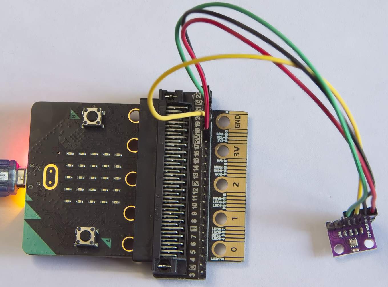
Wiring the Circuit[3]
Make the following connections:
| Step | micro:bit | BMP280 |
|---|---|---|
| 1 | GND | GND |
| 2 | 3V | VCC |
| 3 | pin20 | SDA |
| 4 | pin19 | SCL |
The MicroPython Program
Connect the micro:bit to the computer to power it up. Copy the following program to the MicroPython editor and flash it to the micro:bit.
# Interrogates a BMP280 barometric
# pressure sensor for its ID.
# The correct ID will verify that
# the sensor chip is genuine.

from microbit import i2c, pin19, pin20

# I2C address for BMP280
addr = 0x76
# Register containing ID
ID_CMD = b'\xD0'

# Initialise I2C with defaults:
# freq = 100000
# sda = pin20
# scl = pin19
i2c.init()
# Send command requesting ID.
i2c.write(addr, ID_CMD)
# Read the ID value
value = i2c.read(0x76, 1)
# Convert ID to hexadecimal format.
print('ID Value:', hex(ord(value)))
Click the REPL button to view the output:
Output:
ID Value: 0x58
Success! The id register on the BMP280 does indeed return the correct value of 0x58.
I2C Pros & Cons
Advantages include:
- Simple protocol : It only requires two microcontroller pins.
- Extensible: Allows for easy addition of more devices without additional wiring or pins on the controller.
- Standardised: Widely used with a written standard making the protocol easy to use.
- Low power consumption: Making it suitable for battery-powered devices.
- Flow control: Data frames have built-in flow control bits which makes for reliable transmission.
- Noise immunity: Built-in noise immunity makes it suitable for electrically noisy environments.
Disadvantages include:
- Slow speed: Relatively slow speed compared to comparable protocols such as SPI.
- Limited distance: Very limited range compared to asynchronous UART.
- Addressing complexity: Requires each device on the bus to have a unique address (unlike SPI) which adds to complexity.