GPIO Pins on the micro:bit
Contents
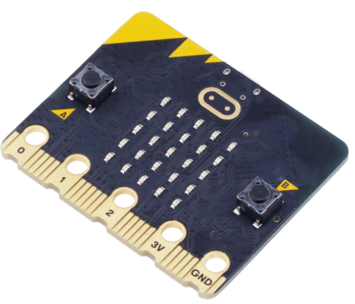
Edge Connector
On the edge of the micro:bit board, opposite the USB connector, are the general purpose input/out (GPIO) pins along with pins for power ('3V') and ground ('GND').
If the user wishes to move beyond the boundaries of the hardware provided on the device (buttons, LED screen, accelerometer, microphone, speaker, and so) and explore the possibilities of interfacing the micro:bit with external devices and sensors, etc. then fitting a third party edge connector breakout board over the native pin interface is a necessity.
There are five pins that are immediately accessible on the micro:bit board; labelled '0', '1', '2', '3V' and 'GND'. They allow connection of 4mm crocodile clips which isn't ideal for breadboard prototyping where the use of DuPont jumper wires is required.
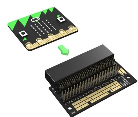
There are a variety of different edge connector breakout boards of varying shapes and sizes on the market to fit the micro:bit - and they are mostly inexpensive, often less than US$10. They are designed to expose every edge pin of the micro:bit as 1 mm diameter round or square pins that are spaced 2.54 mm apart. This is the microcontroller pin connector defacto standard.
GPIO Pin Map
The micro:bit's GPIO pin map is somewhat complicated by the fact that some of the extra hardware (for the educational experience) bundled on the board also use these pins. The graphic below shows how the pins are assigned.
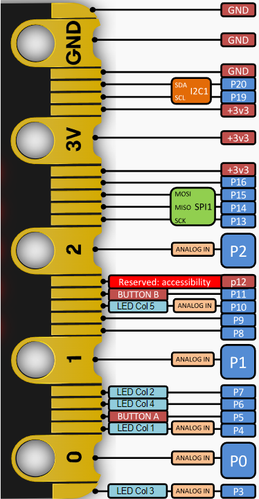
The pins are numbered p0 through to p20 and this is how they are referenced in MicroPython through the microbit module. The pins p17 and p18 don't exist as they are replaced by power pins.
The microbit module instantiates the pins as objects, making each individual pin easy to address. For the reason stated above, p17 and p18 don't exist and will cause an exception (error) to be raised if an attempt is made to address them within the MicroPython program.
Power Pins[1]
There are three pins that supply +3.3 volts and three GND pins. These can be used to provide power to other peripherals and components providing they have low power requirements (sensors, output screens, input devices, LEDs, CMOS/TTL logic chips, etc) though (as always!) care must be taken.
There are four ways to power the micro:bit:
- USB Connection (preferred method).
- Battery plugged into the JST connector (preferred method).
- Via the 3V and GND pins on the edge connector.
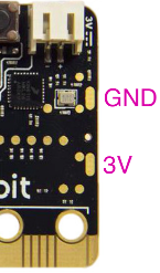
- Via the two rounded rectangular pads on the rear of the board (see Image 4).
Battery and USB power goes through an on-board regulator and is diode protected on the micro:bit V2.
If either option 3 or option 4 is used to power the micro:bit then it is essential that a well regulated 3V to 3.3V supply is used as the on-board voltage regulator is bypassed. It is advisable to install external diode protection to prevent damage from incorrect polarity.
I/O Pins
Not all of the remaining pins are available to the user as I/O pins. Some pins are already in use by the board's hardware goodies; which in some cases can be disabled but in other cases simply shouldn't be used for external interfacing.
Always AvailableThe following pins are always available for general purpose input/output (GPIO):
| Pin | Description |
|---|---|
| pin0 | Digital, Analog (ADC) input |
| pin1 | Digital, Analog (ADC) input |
| pin2 | Digital, Analog (ADC) input |
| pin8 | Digital only |
| pin9 | Digital only |
| pin13 | [2]Digital only |
| pin14 | [2]Digital only |
| pin15 | [2]Digital only |
| pin16 | Digital only |
| pin19 | [3]Digital only |
| pin20 | [3]Digital only |
Disabling the LED Display
If the LED display is disabled then further pins become free for GPIO use. The code snippet below demonstrates the disabling (and re-enabling) of the micro:bit's LED display using the methods display.off() and display.on().
Example 1
# Demonstrate disabling and
# re-enabling the LED display.

from microbit import *
# Show an image on the LED display.
# Wait 3 seconds.
display.show(Image.HAPPY)
sleep(3000)
# Turn off the display
display.off()
# Wait 3 seconds then
# re-enable the display.
sleep(3000)
display.on()
In this example an image will display on the LED display for three seconds. The screen will blank out for three seconds. Then the screen will be turned back on and the image will be seen again.
While the LED display is disabled the following pins become available:
| Pin | Description |
|---|---|
| pin3 | Digital, Analog (ADC) input |
| pin4 | Digital, Analog (ADC) input |
| pin6 | Digital only |
| pin7 | Digital only |
| pin10 | Digital, Analog (ADC) input |
Not for GPIO Use
The following pins should be avoided for GPIO use. They are either unavailable or in use for other functions.
| Pin | Description |
|---|---|
| pin5 | [4]Used by button_a |
| pin11 | [4]Used by button_b |
| pin12 | System reserved |
Thus there are 6 x Analog/Digital pins and 10 x Digital Only pins readily available for GPIO use. This in most circumstance would be sufficient for any hobbyist project.
Digital Read and Write
As noted above, the micro:bit has 16 pins that can be used for general digital input or output.
There are two states (values) of usefulness associated to a digital pin; HIGH and LOW.
If the voltage on the pin is at or close to the circuit voltage (3.3V in the case of the micro_bit) then this state is referred to as HIGH and in code is assigned a value of 1.
If the voltage on the pin is at or close to that of ground then this state is referred to as LOW and is assigned a value of 0 in code.
There is a third possibility where the voltage on the digital pin is neither near the circuit voltage nor ground voltage. This is undesirable and is referred to as floating. This is discussed in the next section.
Digital Read
Using a digital pin for input into the microcontroller is referred to reading i.e. the microcontroller reads the pin state.
When a digital pin is configured for input mode the microcontroller places that pin in a high-impedance state. This means that the pin draws almost no current from the circuit (module, sensor IC, etc) that's connected to the pin. It requires almost no current to move the input pin from one state to another e.g. LOW to HIGH.
The downside is that a digital pin that has nothing connected to it or is connected to a circuit that isn't sending an active signal, can be influenced by electrical noise or capacitive coupling with the state of a close by pin. The pin can be left floating i.e. with an indeterminate or (falsely) changing digital value.
This undesirable state of affairs can be remedied by moving a digital pin to a known state in the absence of a legitimate input. This is done by adding a pullup resistor[5] or pulldown resistor on the input pin.
In the absence of an input, a pullup resistor ensures that the digital pin is in a HIGH state. Likewise a pulldown resistor leaves a digital pin with no input in a LOW state.
According to the Nordic Semiconductor documentation, the micro:bit's nRF52833 microcontroller has both internal pullup and pulldown resistors for its GPIO pins. Most usefully, these pullup and pulldown resistors are configurable at the individual pin level through methods in the microbit library module.
It isn't always necessary to set pullup or pulldown resistors on the digital pin. Some external circuits designed for interfacing to microcontroller pins will contain their own resistors; usually pullups. This is true of many hobbyist's development boards. It's a case of examining the circuit drawing (if available) or physically examining the board. These resistors are usually fairly obvious if present.
With respect to using the digital pin for input, the microbit module has the following methods:
- get_mode() - Get the pin's mode
- set_pull() - Set the status of the pin's pullup/pulldown resistors
- get_pull() - Get the status of the pin's pullup/pulldown resistors
- read_digital() - Read the digital value on the pin
GPIO Pin Mode
The current mode of any I/O pin can be returned with the method get_mode(). The syntax is simple:
Syntax:
pinX.get_mode()

Where:
pinX : name of the pin e.g. pin0, pin16

Returns:
One of the following values:
  "unused", "analog", "read_digital"
  "write_digital", "I2C", "SPI"
  "button", "music", "audio", "touch"

Example:
from microbit import *
mode = pin5.get_mode()
print('pin5 mode is:', mode)
⇒ pin5 mode is: button
Pin pullup and pulldown Resistors
The method set_pull() causes the microcontroller to set the requested resistor configuration.
Syntax:
pinX.set_pull(value)

Where:
pinX  : name of the pin e.g. pin0, pin16
value : resistor configuration, one of;
  pinX.PULL_UP
  pinX.PULL_DOWN
  pinX.NO_PULL

Note: This method forces the pin mode
      to "read_digital".
If the set_pull() method is not invoked then a digital pin in "read_digital" mode by default will have the pulldown resistor set.
The method get_pull() returns the status of the internal resistors on the pin.
Syntax:
pinX.get_pull()

Where:
pinX : name of the pin e.g. pin0, pin16

Returns:
One of:
  0 : which is PULL_UP
  1 : which is PULL_DOWN
  2 : which is NO_PULL

Note: The pin must be in "read_digital"
      mode otherwise an exception (error)
      will be raised.

Example 1:
# This will cause an error because the pin
# is not in "read_digital" mode.
from microbit import *
mode = pin2.get_mode()
print(mode) ⇒ unused
pull = pin2.get_pull()
print(pull)
⇒ ValueError: Pin 2 in unused mode

Example 2:
from microbit import *
mode = pin2.get_mode()
print(mode) ⇒ unused
# Force the pin into "read_digital" mode.
pin2.set_pull(pin2.PULL_DOWN)
pull = pin2.get_pull()
print(pull) ⇒ 1
Read the Digital Pin Value
This is done simply with the read_digital() method.
Syntax:
pinX.read_digital()

Where:
pinX : name of the pin e.g. pin0, pin16

Returns:
One of:
  0 : LOW value
  1 : HIGH value

Example:
from microbit import *

def print_data(pin, value):
    if value == 0:
        print(pin, 'value is LOW')
    else:
        print(pin, 'value is HIGH')
    print()

# Put Pin 8 into "read_digital" mode
# with pulldown resistor set.
pin8.set_pull(pin8.PULL_DOWN)
print('Pulldown resistor set')
# Read the signal on the pin
data = pin8.read_digital()
print_data('Pin 8', data)

# Put Pin 8 into "read_digital" mode
# with pullup resistor set.
pin8.set_pull(pin8.PULL_UP)
print('Pullup resistor set')
# Read the signal on the pin
data = pin8.read_digital()
print_data('Pin 8', data)

Output:
Pulldown resistor set
Pin 8 value is LOW

Pullup resistor set
Pin 8 value is HIGH
Digital Write
If the microcontroller places a digital signal on a pin then this is referred to as writing i.e. the microcontroller writes a digital value of 0 (LOW) or 1 (HIGH) to the pin.
This is done with the write_digital() method.
Syntax:
pinX.write_digital(value)

Where:
pinX  : name of the pin e.g. pin0, pin16
value : digital value to write to the pin.
        One of:
          0 : This is the LOW value
          1 : This is the HIGH value

Example:
from microbit import *

LOW = 0
HIGH = 1

def print_data(pin, value):
    if value == LOW:
        print(pin, 'value is LOW')
    else:
        print(pin, 'value is HIGH')
    print()

# Write to the pin
print('Write LOW to Pin 8')
pin8.write_digital(LOW)
# Read the pin value.
# Must set NO_PULL first so that
# the written value isn't changed.
pin8.set_pull(pin8.NO_PULL)
value = pin8.read_digital()
print_data('Pin 8', value)

# Write to the pin
print('Write HIGH to Pin 8')
pin8.write_digital(HIGH)
# Read the pin value.
# Must set NO_PULL first so that
# the written value isn't changed.
pin8.set_pull(pin8.NO_PULL)
value = pin8.read_digital()
print_data('Pin 8', value)

Output:
Write LOW to Pin 8
Pin 8 value is LOW

Write HIGH to Pin 8
Pin 8 value is HIGH
The above example illustrates an important point. If the external circuit (such as in the above example) is capable of writing both High and LOW values to the pin then it is usually important that the pullup/pulldown resistors aren't set when the program reads the digital pin - accomplished by using the method (where pinx is the name of the pin):
pinx.set_pull(pinx.NO_PULL)
If the external circuit connected to the digital pin writes a LOW to the pin when a condition is met then it is important that the pin is initialised with the pullup resistor set so that the pin is normally HIGH till the external circuit pulls it LOW.
pinx.set_pull(pinx.PULL_UP)
Likewise, if the external circuit connected to the digital pin writes a HIGH to the pin when a condition is met then it is important that the pin is initialised with the pulldown resistor set so that the pin is normally LOW till the external circuit pulls it HIGH.
pinx.set_pull(pinx.PULL_DOWN)
In all cases it is important that the pin isn't left in an indeterminate state i.e. floating.
Analog (ADC) Read
The micro:bit has six analog capable GPIO pins: pin0, pin1, pin2, pin3, pin4 and pin10.
Each of these pins are internally connected to an analog to digital converter (ADC). The ADC converts an analog voltage that an external circuit is applying to the pin; expected to be between 0V and +3.3V; to a value between 0 and 1023 (i.e. a 10 bit digital value).
The method read_analog() is provided in the microbit module for reading the pin's analog voltage then returning it as an integer value between 0 and 1023.
Syntax:
pinX.read_analog()

Where:
pinX  : name of the pin e.g. pin0, pin16

Returns:
Integer value between 0 and 1023

Example:
from microbit import *
value = pin2.read_analog()
If required, the ADC integer value can be converted back to the pin's voltage with the following formula:
V = ADC/1024 * 3.3
Where: ADC is the value between 0 and 1023 returned by the analog to digital converter on the pin.
Since the micro:bit's ADC's are 10-bit this gives an analog resolution of approximately 3.2mV.Pulse Wav Modulation (PWM)
What is PWM?The pins of a micro:bit, designated as analog, are analog read only i.e. the voltage applied to the pin by an external circuit is read and returned as an integer between 0 and 1023. The microcontroller can only pull-up these pins to (around) 3.3V or pull-down these pins to 0V. It cannot output an analog voltage signal between these HIGH and LOW limits.
However using a technique called Pulse-Width Modulation (PWM) the analog pins can simulate an analog voltage output which is suitable for tasks such as controlling the speed of an electric motor or the brightness of an LED.
PWM involves rapidly switching the voltage on and off. PWM is controlled with two parameters:
- Period
- Duty cycle
Period and Duty Cycle
PWM outputs a square wave. The period is the time taken for one cycle of the square wave. It is measured in microseconds or milliseconds.

One cycle consists of:
- The voltage rises very rapidly from LOW to HIGH
- The voltage remains high for time TH
- The voltage drops very rapidly from HIGH to LOW
- The voltage remains LOW for time TL
The duty cycle is the proportion of time that the square wave is at HIGH during one cycle (period). The greater the time the pin is held HIGH then the higher is the apparent voltage seen on the pin.
So by definition:
Period = TH + TL
Which leads to the definition of duty cycle (%):
Duty Cycle = TH/Period x 100
PWM Examples
Three examples of PWM are shown in Image 6. Each example is an oscilloscope[6] trace showing a single square wave. The period of the square wave in all three examples is 1 millisecond (1000 microseconds) with each major axis time line representing 500 microseconds.
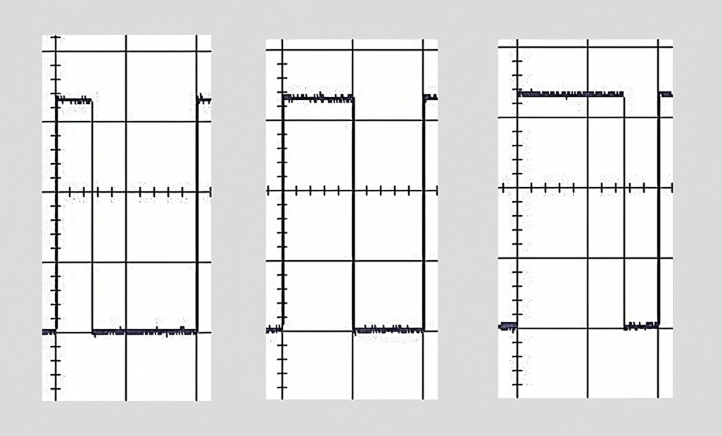
The left-hand trace has the square wave at HIGH for 250 microseconds thus the duty cycle is 25% (250/1000 x 100). Likewise the middle trace has the wave at HIGH for 500 microseconds so the duty cycle is 50% (500/1000 x 100). And finally, in the right-hand trace the wave is at HIGH for 750 microseconds giving a duty cycle of 75% (750/1000 x 100).
The full oscilloscope scan of a PWM signal from a microbit analog pin is shown in Image 7. The period = 1 millisecond and the duty cycle = 75% i.e the pin is HIGH for 75% of the time.
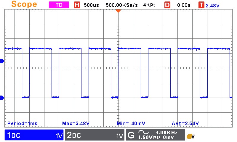
The statistics displayed by the oscilloscope are interesting and worth commenting on:
- The measured period of 1 ms shows precise control of the square wave by the micro:bit.
- The maximum voltage was measured at 3.48V, showing some small fluctuation of a nominal 3.3V from the micro:bits's onboard voltage regulator. The micro:bit was powered from a laptop's USB port.
- The average measured voltage of 2.54V is the apparent voltage that an external circuit connected to the micro:bit's pin would experience. This is 75% of the average HIGH voltage.
The micro:bit can simultaneously and independently provide PWM signals on a maximum of three analog pins. This means that each pin programmed for PWM can be configured with its own period and duty cycle. Attempting to use PWM on a fourth analog pin does not throw an exception (error) but does give unpredictable results. Best not to try it!
PWM MicroPython Methods
The following methods are provided by the microbit module for invoking PWM on the micro:Bit:
- set_analog_period()
- set_analog_period_microseconds()
- get_analog_period_microseconds()
- write(analog)
Setting the PWM Period
Syntax: (milliseconds)
pinX.set_analog_period(period)

Where:
  period : The PWM period in milliseconds.
           Minimum value is 1ms.

Syntax: (microseconds)
pinX.set_analog_period_microseconds(period)

Where:
  period : The PWM period in microseconds.
           Minimum value is 256us.
Getting the PWM Period
Syntax:
pinX.get_analog_period_microseconds()

Returns:
  Returns the period in microseconds that has
  been set by either of the two methods above.

Example:
from microbit import *

# Set pin0 PWM period to 5ms
pin0.set_analog_period(5)
# Get the period
P0 = pin0.get_analog_period_microseconds()
print('pin0 period (us) =', P0)

# Set pin1 PWM period to 300us
pin1.set_analog_period_microseconds(300)
# Get the period
P1 = pin1.get_analog_period_microseconds()
print('pin1 period (us) =', P1)

⇒ pin0 period (us) = 5000
⇒ pin1 period (us) = 300
NOTE: Exercise caution with the get_analog_period_microseconds() method. Under certain circumstances it will return erroneous results.
Set Duty Cycle and Initiate PWM Signal
Before initiating the PWM signal on the pin, the period must firstly be set using one of the two methods described above.
After the period is defined, both the duty cycle is set and the PWM signal is turned on with a single call to the write_analog() method.
The duty cycle required is passed to this method. In the discussion so far, duty cycle has been referenced as a percentage (%). However this method expects the duty cycle to be given as an integer value between 0 and 1023. The conversion is a simple matter.
As an example, if a duty cycle of 65% is required then the value passed to write_analog() would be:
int(65/100 * 1023)
= 664.
Syntax:
pinX.write_analog(value)

Where:
  value : The duty cycle of the PWM signal given
          as an integer between 0 and 1023.

The PWM signal will appear on the pin with the
given period (set beforehand) and duty cycle.

Example:
# This example will output a PWM
# signal on pin0 with a period of 260us
# and a duty cycle of 65%.

from microbit import *

period = 260 #us
duty_cycle = int(65/100 * 1023)

# Set period
pin0.set_analog_period_microseconds(period)
# Set duty cycle and start PWM.
pin0.write_analog(duty_cycle)
The resultant PWM waveform from the example program above and captured by an oscilloscope is shown in Image 7.
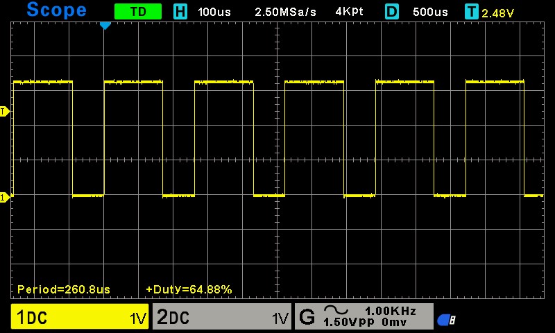
The statistics show impressive PWM output control by the micro:bit with an average period of 260.8us and a duty cycle of 64.88%.