Breadboard Power Supply Options
Contents
Introduction
The most obvious power supply option for the breadboard are the power pins on the microcontroller board. Nice, simple, easy to use and the ideal solution for many peripherals such as low current sensors.
Several problems can arise while using the microcontroller as the power source:
- The microcontroller board mightn't be able to supply enough power for the breadboard circuit. The micro:bit V2 specifications state that the on-board 3.3V regulator can supply up to 300mA.
- Inductive load components such as electric motors can induce large flyback voltages when its power supply is abruptly removed. This has the possibility of damaging the microcontroller chip especially if flyback diodes aren't used.
- The micro:bit power pins supply 3.3V. Some componentry may require a different operating voltage. There are still devices out there that require a 5V source.
So there are occasions when alternatives to the microcontrollers power pins must be considered. This webpage explores some commonly used options.
MB102 Breadboard Power Supply
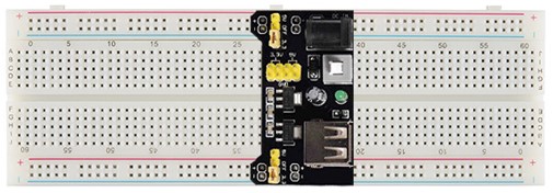
The MB102 Breadboard Power Supply is a module specifically designed to power a breadboard. Its footprint and the placement and diameter of the output power pins allows it to securely plug into an MB102 breadboard that has dual power rails.
It can supply 3.3V and/or 5V to the breadboard power rails.
Power In
There are two different methods for powering the MB102 module:
- USB Device Connector
- Any 5V USB source can be plugged into the onboard USB socket.
- This source directly powers the board's 5V output pins.
- It is also routed through an A1117-3.3 voltage regulator which supplies the 3.3V output pins.
- There is no surge protection, so the USB socket should not be powered from a computer's USB port.
- Since there is no reverse polarity protection, the USB socket (when powered through the barrel connector) will provide 5V to external devices.
- DC barrel socket (5.5mm x 2.1mm)
- Can accept any voltage in the range of 6.5V to 12V.
- The centre pin is +ve and the outside surface is -ve polarity.
- An IN4007 diode is used for reverse polarity and surge protection.
- The input from the barrel socket is routed through:
- An A1117-5 voltage regulator to the 5V output pins.
- An A1117-3.3 voltage regulator to the 3.3V output pins.
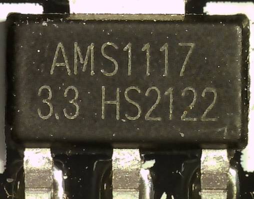
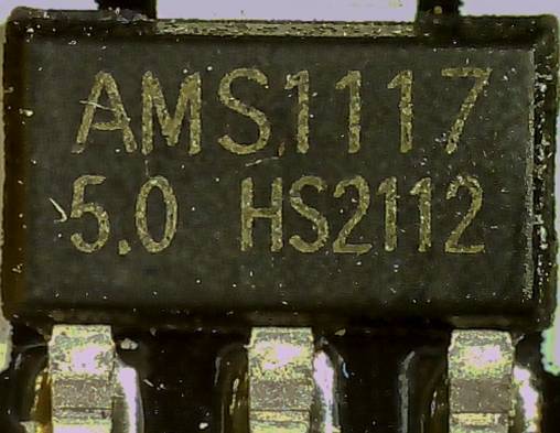
Fig 2 - Micrograph of the A1117-3.3 and A1117-5 voltage regulators on the the MB102 power supply module
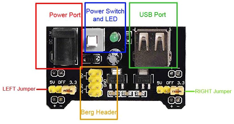
There is a double pole, double throw switch which when depressed isolates both input power sources. Located next to the switch is a green LED that indicates whether the board is powered or not.
Power Out
On the underside of the module on each side there are pairs of power output pins that are spaced to fit the power rails of the breadboard. When these pins are pushed into the breadboard the module sits firmly and securely across the breadboard.
NOTE: Care must be taken that the module is connected with the correct polarity to the breadboard. The output pins that plug into the breadboard are labelled + and -. Ensure that these match the + and - on the breadboard power rails.
Each power rail can, independently of the power rail on the opposite side of the breadboard, be supplied with either 0V, 3.3V or 5V. This is achieved by setting left-side and right-side jumpers on the power module for the voltage required (see Fig 3).
Additionally, the board contains a Berger Header with 2 x 5V pins, 2 x 3.3V pins and 4 x GND pins. These can be used to power external devices off the breadboard.
The maximum output current that the MB102 power module can source is around 700 mA.
Quick Test
A MB102 power module was plugged into a breadboard. Power from a 7.5V AC adapter was applied through the barrel connector.
The jumpers were set such that one power rail received 5V and the other power rail was at 3.3V.
Each power rail was connected to a separate channel on an oscilloscope. The stability of each voltage was monitored.
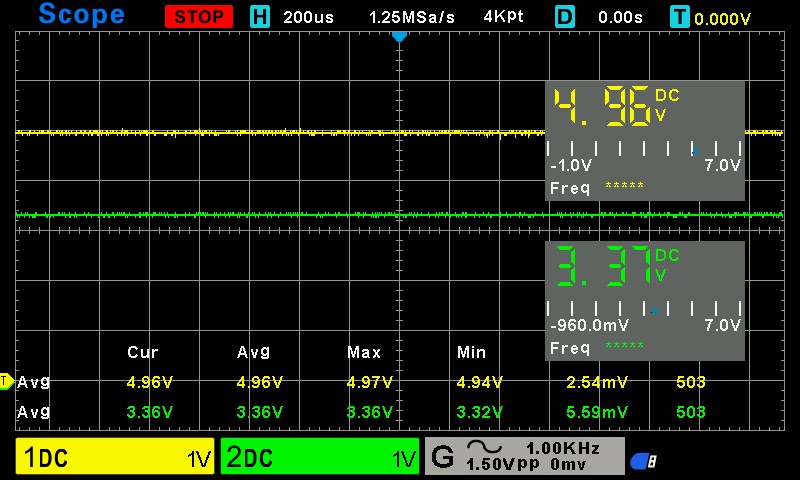
Bearing in mind that no load was applied, the voltage in both cases was acceptably stable.
The following results were recorded after a statistical analysis of 500 samples:
| Voltage | Average | Maximum | Minimum | RMSE[1] |
|---|---|---|---|---|
| 3.3V | 3.36V | 3.36V | 3.32V | 5.59mV |
| 5V | 4.96V | 4.97V | 4.94V | 2.54mV |
[1] RMSE = Root Mean Square Error
More Breadboard Power Supply Options
Batteries
It's a simple task to power a breadboard with just about any portable battery. Push a terminal connector onto the top of the battery or push the battery into a suitable battery case. Then push the red lead into the +ve row of the power rail and the black lead into the negative row. The breadboard now has a power source.
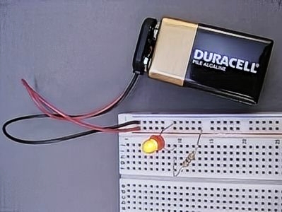
This will usually work fine to power a microcontroller breakout board because the breakout board will nearly always have a voltage regulator included.
However the breadboard might be used with components that have specific voltage requirements: voltage level and stability of supply:
- The battery voltage may not be suitable for the circuit being built.
- The voltage slowly reduces as the battery drains which may affect the performance of the circuit.
This problem can sorted with the use of voltage regulators and buck converters. These are discussed below.
The obvious advantage of using a battery as the power source is the portability of the project.
USB Chargers and Power Banks
Anybody who is wanting to power a breadboard will have USB chargers (power bricks) on hand. USB adapters with pins to fit breadboards are inexpensive and readily available.
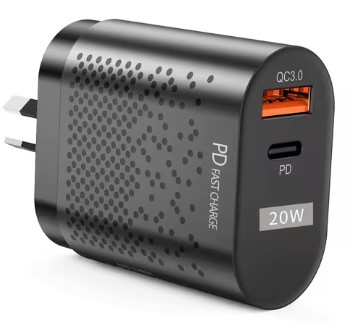
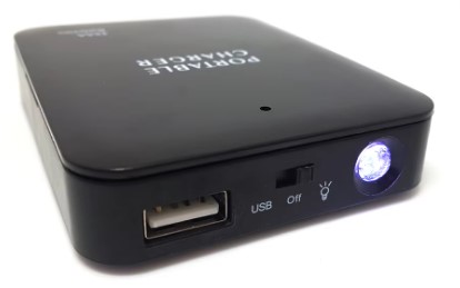
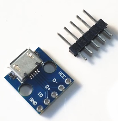
Fig 6 - [L to R] USB wall charger, USB power bank, USB breadboard adapter
USB power banks work in exactly the same way but with the advantage of making the project portable.
USB chargers and power banks will supply 5V DC. If any other voltage (e.g. 3.3V) is required then a voltage regulator or buck converter will do the job. These are discussed below.
Other AC Adapters
There are many other types of AC adapters available. Mostly they have jacks meant to be inserted into barrel connectors (Fig 7). There are two basic types:
- Fixed voltage e.g. 9V or 12V
- Multi-voltage (Fig 7) which offer a selectable choice from a range of fixed voltages.
- Adapters with selectable voltages of 3V, 5V, 7.5V, 9V and 12V are quite common.
- The desired voltage is selected by turning a click-dial on the adapter body
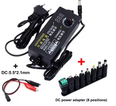
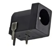
Fig 7 - [L to R] Multi-voltage AC adapter with accessory barrel adapters, breadboard-friendly barrel jack connector
Breadboard friendly barrel connectors (Fig 7) are inexpensive and readily available.
If any other voltage (e.g. 3.3V) is required then a voltage regulator or buck converter will do the job. These are discussed in the next section.
Voltage Regulators
If the supply voltage is incorrect and/or not particularly stable then the most economical solution is the use of a voltage regulator. A voltage regulator is a circuit that creates and maintains a fixed output voltage, irrespective of changes to the input voltage or load conditions.
There are two broad classes of voltage regulators:
- Linear Regulators
- Switching Regulators
Linear Voltage Regulators
Linear regulators are always step-down converters i.e. the output voltage is less than the input voltage. The input voltage needs to be a minimum of 1-2 Volts above the output voltage.
They also have low efficiency with the consequence they can get very hot. If driven near their datasheet capacity an external heat sink will need to be attached to the regulator.
Linear regulators, however, have some compelling advantages and are usually the choice for projects with low power requirements. They respond very quickly to input voltage change so the output voltage is almost ripple free.
They are inexpensive, being a US dime (10¢) or less per unit. They are available for all common circuit voltages.
A variation of the linear voltage regulator is the low-dropout regulator (LDO) which can work with in input voltage only several hundred millivolts above the output voltage.
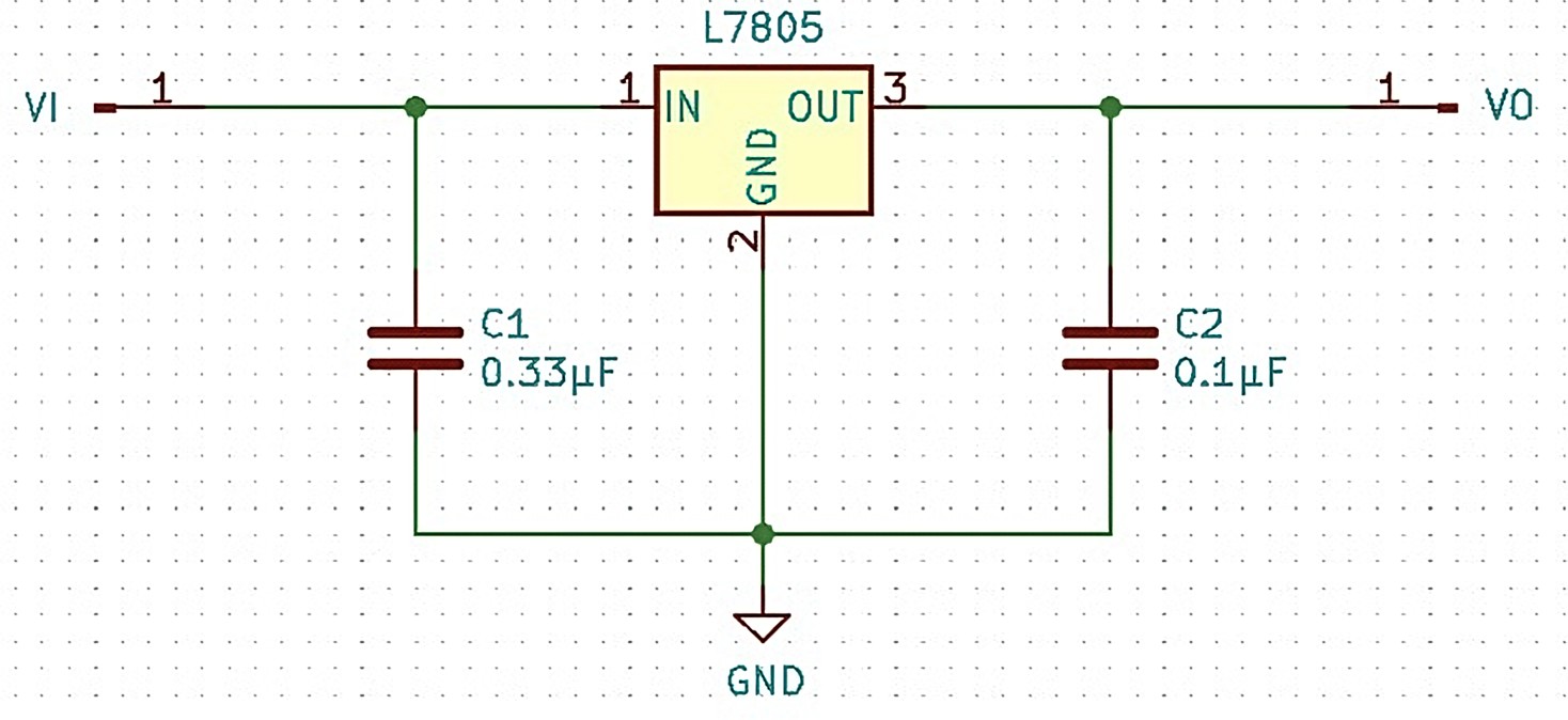
They are also simple to use. The only additional components usually required are two capacitors for input and output line filtering respectively.
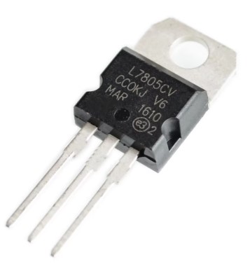
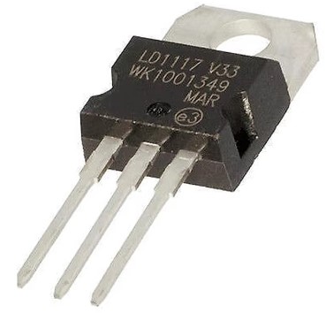
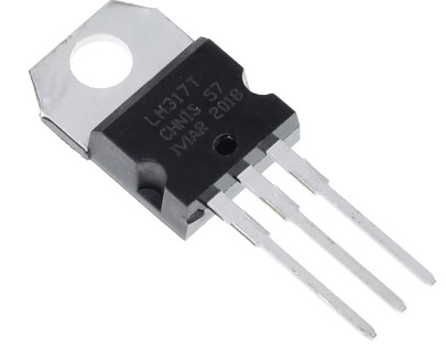
Fig 8 - [L to R] Linear voltage regulators: L7805, LD1117 and LM317
- L7805 : Input 7V to 35V, Output fixed 5V.
- LD1117 : LDO regulator, Input 4.5V to 15V, Output model selection of fixed 1.2V, 1.8V, 2.5V, 2.85V, 3.3V and 5.0V
- LM317-x : Input 3V to 40V, Output variable with external voltage divider of two resistors 1.25V to 37V.
Switching Regulators
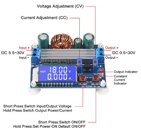
Switching regulators are more complex than linear voltage regulators but are much more efficient, often >95%, so generate much less heat. This means that they can handle heavier loads.
The increased complexity comes with a higher cost, potential for noise generation and require careful design to ensure stable operation. Most hobbyists will purchase these as a module with all additional components already installed on the board.
There are switching regulators that step down voltage (buck converter) and switching regulators that step up voltage (boost converter). Both types offer adjustable output voltage and current.
Bench Power Supplies
This is the "Rolls-Royce" solution for just about any DC power requirement. They are a desktop/laboratory bench box that is powered from an AC powerpoint. Some designed for very specific purposes output a single fixed voltage. However most bench power supplies have a voltage output that is user selectable in increments of 10mV or finer.
All but the very cheapest units will have CV mode (constant voltage) that ensures the set voltage is maintained even under heavy load. Many also have a CA mode (constant current) where the voltage is controlled to ensure a constant current is passed through a load.
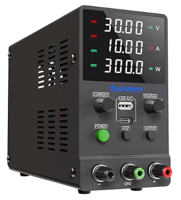
Until quite recently these power units were usually large, heavy and expensive. However, prices (and size) have dropped with improved performance. They are capable of a much larger power output then any of the the options discussed above.
Considering the cheaper alternatives the bench power supply is expensive if just to be used to power a breadboard. However if there are other uses it can be put to, then a bench power supply can represent good value.