TM1637 Driving 7-Segment LED Displays
Contents
Introduction
This article is about the popular TM1637 LED display driver chip. But firstly there needs to be an introduction to the 7-segment LED 'tube'; the basic unit of all LED digit displays.
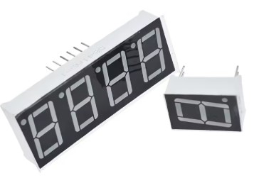
This naturally leads onto the connection of four of these units to make a 4-digit LED display. These have been popular display units for decades. The big problem though, is the large number of microcontroller pins and processing power required to operate the 4-digit LED display.
This issue was solved a long time ago with the development of dedicated chips (known as 'drivers') that are dedicated to the task of doing just this. They are generally inexpensive and easy to use. The TM1637 is such a chip, specifically designed for driving a 4-digit LED display.
7-Segment LED Digital 'Tube'
Everyone will be familiar with the 7-segment LED display. They are still commonly used in digital clock displays. Unlike other display technologies they don't require a backlight for night time viewing and the brightness of the display is easy to adjust for different ambient lighting conditions.
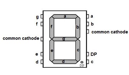
A seven-segment display is made of seven individual LED illuminating segments labelled 'a' through to g. All the digits from 0 through to 9 can be displayed by selecting which LED segment glows.
For example; to display the digit '3' the LED segments 'a', 'b', 'c', 'd' and 'g' are lit. In practice a simple lookup truth table is used to determine which segment needs turning on for any given digit. There are also separate BCD decoder chips available that will do this.
The problem with controlling these units with a microcontroller should be obvious. Each LED 7-segment single digit unit requires eight digital pins (seven for the digit and one for the decimal point). Adding more digits to display a larger number will soon become impossible to control with most microcontrollers. The sheer number of digital pins required for control soon becomes a limiting factor.
4-Digit LED Displays
LED 7-segment 4-digit displays are commonly available that can display any number from -999 through to 9999. Additionally there is usually a decimal point (DP) after every digit allowing floating point numbers to also be displayed.
A useful variant for use as a clock display has a colon between the second and third digits. These often (but not always) dispense with the decimal points.
In order to control four LED 'tubes' based on the scenario described above it would require 32 microcontroller digital pins. This simply isn't feasible. However the 4-digit LED displays use a clever multiplexing trick. See Fig 3 below.
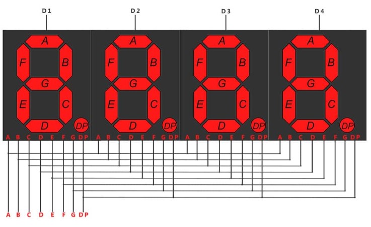
One set of 7-segment pins ('a' through to 'g') is shared across all 4-digits. There are an additional four pins, labelled 'D1', 'D2', 'D3' and '4' that control which digit's 7-segment array is being accessed.
For example: if the 'D1' line is pulled HIGH[1] and 'D2', 'D3', 'D4' are kept LOW then the required segments of the rightmost 'tube' can be illuminated to form the required digit.
In this manner all four digits can be displayed by pulling HIGH the appropriate selector pin in turn and writing the 7-segment pattern to the selected digit.
This multiplexing arrangement has a down side. The display needs regular refreshing at a rate such that a human won't see it flicker. The acceptable rate is 60Hz i.e. 60 times per second. This means that on average all four digits must be refreshed about every 17 milliseconds!
Modern microcontrollers can do this OK. But it eats into the time required for other tasks. Also, while the need for 32 digital pins has been alleviated with this multiplexing method, it still does use 12 digital pins.
In general the usual way to solve such problem is to design separate specialised hardware to take over the task from the microcontroller. And this is exactly what has happened in the case of LED 7-segment displays. Most of the chips that have made it to market are inexpensive and easy to use - win/win.
The next section describes such a chip - the TM1637.
TM1637 LED Display Driver
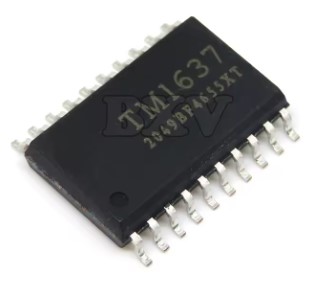
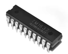
The TM1637 from Titan Micro Electronics can drive up to six multiplexed LED 7-segment 'tubes' (digits) simultaneously. While six digit multiplexed LED 7-segment units are available it is more usual to see this chip driving a four digit display.
The TM1637 can also be used to scan an 8x2 matrix keyboard. However that capability won't be discussed further here.
Through multiplexing the TM1637 is only supplying power to one digit at any time. This means that the current draw is quite low. It is claimed that the maximum current draw is only 85mA. Thus a micro:bit V2 should be able to power up to three of these 4-digit LED 7-segment displays quite comfortably providing no other power intensive peripheral is attached.
These chips are CMOS technology so may be used with 3.3V and 5V microcontrollers. They are available in DIP-20 and SOP-20 packaging.
The hobbyist usually purchases the TM1637 and 4-digit LED display as a module. They are readily available in two forms - decimal point after each digit or colon between the second and third digits for time display - as shown in Fig 4.
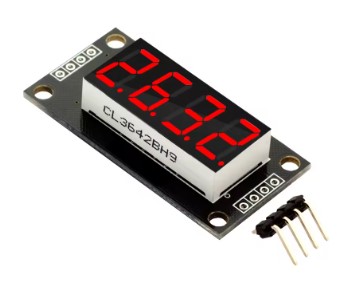
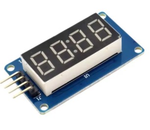
Fig 4 - TM1637 driven 4-digit LED display units
The TM1637 has a propriety two-wire serial interface that is quite similar to I2C. However it does not follow the I2C standard. The datasheet describes the interface quite well and in practice it is easy to use.
Since it isn't standard I2C the user program will need to code the low level 'bit-bashing' methods to send the start bit, data & command bytes and stop bit.
There is a 6 byte Display Address register with each byte dedicated to a 7-segment digit. Thus in the case of a 4-digit display only 4 bytes of this display register is written to by the MicroPython driver. The basic algorithm to update the 4-digits of the display is quite simple:
- Assemble the 8-bit structure for each of the digits in microcontroller memory.
- Issue the Write Data command to the TM1637.
- Send the start address of the TM1637's Display Address register.
- Write digit display bytes to the TM1637's Display Address register.
- The TM1637 will update the LED display after all display bytes have been written.
The TM1637 can also control the brightness of the display. It accomplishes this by altering the time that each LED segment is powered on - known as pulse width - during each display refresh. There are eight selectable brightness levels to choose from by writing a value in the range 0 to 7 to the TM1637's Display Control register.
MicroPython TM1637 Driver for micro:bit
A MicroPython driver library for a TM1637 controlled 4-digit LED 7-digit display written specifically for the microbit is available as part of this web series.
The driver, written as a class, allows the user to the declare a TM1637 object with methods to:
- Display an integer or float value
- Display a 24Hr time in the format of 'hh:mm'
- Set the display brightness
This driver allows multiple TM1637 displays to be connected to a micro:bit. Each display only requires two micro:bit digital pins (plus 3.3V and GND).