DS1307 Real Time Clock
Contents
DS1307 Description
The datasheet describes the DS1307 serial real-time clock (RTC) as a low-power, full binary-coded decimal (BCD) clock/calendar plus 56 bytes of NV SRAM
.


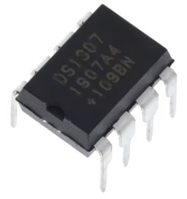
Fig 1 : The DS1307 RTC chip and its pinout
It operates on a voltage range of 4.5V to 5.5V. It's for this reason that most MicroPython developers for the micro:bit (3.3V) wouldn't bother with this chip. There are far better alternatives available that also match the voltage on the micro:bit.
The DS3231 RTC chip is such an alternative. The following table compares the DS1307 against the DS3231.
| DS1307 | DS3231 | |
|---|---|---|
| Supply voltage | 4.5V to 5.5V | 2.3V to 5.5V |
| Battery backup | 2.0V to 3.5V | 2.3V to 5.5V |
| Accuracy | Circuit dependant, ±20ppm typically |
±2ppm |
| Oscillator | External | Internal |
| Temperature compensated | X | ✓ |
| Time: seconds, minutes, hours |
✓ | ✓ |
| 12/24 Hr clock | ✓ | ✓ |
| Calendar: day, month, year (00-99), day of week |
✓ | ✓ |
| Alarms | X | 2 |
| Square wave output pin | ✓ | ✓ |
| Temperature sensor | X | ✓ |
| User nonvolatile RAM | 56 bytes | X |
| Serial interface | I2C | I2C |
The DS1307 with its external oscillator circuit will never match the accuracy of the DS3231 clock with its temperature compensated internal oscillator.
Just about the only reason for interfacing the DS1307 with the micro:bit is to experiment with logic level shifters. With the disparity in supply voltages (3.3V Vs 5V) it is essential to use some sort of level shifter.
The best option for the hobbyist is probably the BSS138 MOSFET based logic level shifter breakout board.
DS1307 Breakout Board
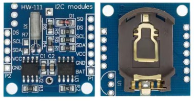
Rather than just using the bare chip, it's usually much more convenient for the hobbyist to purchase the DS1307 on a breakout board. FIG 2 shows such a board, widely available for a (very) few dollars.

There is provision on the back of the board for a backup battery. The recommended battery is a CR2032 coin cell, which is commonly used in PCs and other electronics hardware for RTC backup. The DS1307 consumes less than 0.5µA when in battery mode so one such lithium cell battery could be expected to provide backup power for at least 10 years.
As already stated, the micro:bit's 3.3V is insufficient to directly power the DS1307. However the DS1307's I2C bus will respond to a bus scan at this voltage even though the clock's register are unavailable for read or write operations.
AT24C32 EEPROM
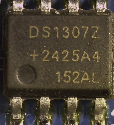
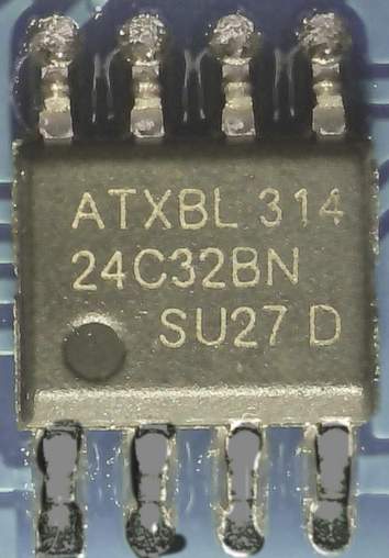
The 8-pin chip on the left-hand side of the board in Fig 2 is the DS1307. The other 8-pin chip (right-hand side of the board) is an AT24C32 EEPROM. This is not part of the RTC functionality; it's provided purely for the user to store custom non-volatile data. The datasheet for the AT24C32 states that it is good for one million write cycles. While given that, it is not considered good practice to continually write to an EEPROM, for example using it as a logger for rapidly collected sensor data.
The AT24C32 provides 4KB of non-volatile memory. It is accessed by the same onboard I2C interface that's used to communicate with the DS1307. It has a default address of 0x50 on this board but that can changed by soldering combinations of the jumper pads A0, A1 and A2.
Interestingly, the AT24C32 will function perfectly well with a 3.3V power supply thus can be driven directly by the micro:bit.
The driver provided with this webpage does not cover the AT24C32, so it will not be discussed further.


Fig 3 - Micrograph view of DS1307 and AT24C32 chips on the breakout board
DS1307 Breakout Board Pinout
The following pins of the DS1307 chip are brought out on the module board:
- VCC - Connect to 5V supply
- GND - connect to GND of the 5V supply
- SDA - I2C data line
- SCL - I2C clock signal
- SQ - Outputs one of four square wave frequencies (1Hz, 4kHz, 8kHz, 32 kHz) at 5V
- BAT - Connected to the VBAT pin of the chip
The SCL and SDA pins are at 5V so cannot be directly connected to the micro:bit pins. Instead they must be connected to pin19 and pin20 (respectively) on the micro:bit through a logic level shifter. This is described in some detail on the DS1307 driver page that accompanies this webpage.
The DS pin is separate to the DS1307 chip. Looking at Fig 2, on the bottom-left corner of the board next to the battery holder is a 3-pin connector point labelled U1. A DS18B20 temperature sensor chip can be soldered here.
This temperature sensor uses a 1-wire serial interface that is tricky to implement in MicroPython on the micro:bit. The DS pin connects to the data pin of the sensor if a DS18B20 chip is soldered to the board.
The pins on the other end of the board (SCL, SDA, VCC and GND) allows daisy chaining of another I2C slave.
The DS1307 Clock
The DS1307 clock has registers that can be written and read via I2C for:
- Seconds (00 - 59)
- Minutes (00 - 59)
- Hour (00 - 23)[1]
- Day of Week (01 - 07)
- Calendar Day (01 - 31)
- Month (01 - 12)
- Year (00 - 99)
The Day of Week can be set to start on any week day. At midnight the Day of Week is incremented. After the seventh day it wraps around to Day of Week = 1. This is equivalent to the WEEKDAY concept in Microsoft Excel.
The contents of the time and calendar registers are in BCD (binary coded decimal) format. BCD is widely used in digital electronics.
In BCD, each decimal digit (0 to 9) is converted into a four-digit binary code (0's and 1's).This makes for very easy and efficient conversion between decimal and binary representations[2].
MicroPython Driver for micro:bit
The original driver written by Shaoziyang can be found on GitHub (https://github.com/shaoziyang/microbit-lib/tree/master/misc/DS1307). This driver is well-coded.
An extended version has been developed as part of this series on MicroPython for the microbit. This page also provides a detailed description of the driver's methods with sample code.
Since the DS1307 RTC operates at 5V the driver page also provides instructions to interface with the micro:bit through a logic level shifter.
The driver is implemented as a class. This is by far the most versatile approach as a program can use the class to instantiate more than one physical DS1307 module, each independent of the other. It is also easy for a knowledgeable user to extend the class.
Reading and Setting the Clock
Methods are provided set and read the seven date and time registers. Methods are available to obtain the time and date in formatted strings that Microsoft Excel recognises. This makes it easier to import logged data into Excel for further analysis.
Accessing DS1307's User RAM
The driver also provides a simple method to read and write the 56 bytes of user RAM on the DS1307 chip.