OpenLog Serial Data Logger
Contents
Introduction
This series is specially aimed at using the BBC micro:bit. While this article is written with a micro:bit flavour most of what follows is applicable to any capable microcontroller platforms.
One of the many useful things a microcontroller can do is interface with sensors and return live readings. Writing the results out to the MicroPython REPL, LCD display or LED 7-segment display might be all that is needed if just exploring the sensor as an educational project.
However the data collected by the microcontroller from any number of sensors may need to be analysed further e.g. in a spreadsheet and/or published or otherwise be reported. In this case the microcontroller needs some sort of removal storage or data transfer technology to enable collection of the readings to a computer.
WiFi might be an option for data transfers. However specifically in the case of the micro:bit this is not viable unless a third party wireless module can be found that will work with this platform. Unfortunately the proprietary radio stack provided as a component of the micro:bit's board is next to useless for any serious work.
Fortunately there is a better solution. The most common removable storage technology used by embedded systems is the SD (or microSD) card. These cards have many advantages:
- Readily available and inexpensive.
- A large variety of different capacities are available including high-end cards that rival the storage capacity of SSDs.
- Capable of being read by many devices including phones, tablets and computers with the use of adapters and readers.
- Specifically for microcontrollers:
- Interfacing hardware for a variety of platforms is now available
- Downloadable (driver) software libraries are readily available.
- Low power requirements
They are slower, especially for writing, than storage solutions such as SSDs and HDDs. This will rarely be a problem though as the volume of data written is also comparably much smaller. That said, newer higher class SD cards come with very impressive burst write speeds.
OpenLog Description
There is an excellent microSD card interface solution available for the micro:bit. The OpenLog serial data logger is as the name suggests not just a microSD interface board but a complete data logging solution.
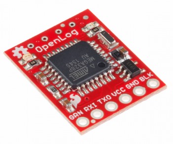
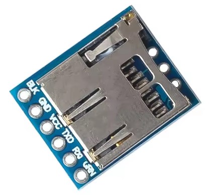
The OpenLog is based on the 8-bit AVR ATmega328P. This is the same microcontroller found in the Arduino UNO. The OpenLog can be powered in the range of 3.3V to 12V though the documentation recommends either 3.3V or 5V. It is low power even when writing to the MicroSD card so can be safely powered from the micro:bit's 3.3V pins.
As the name suggests the SparkFun designed OpenLog is completely open source so can be copied by anybody. It comes with the Optiboot serial bootloader preinstalled. This is the default Arduino boot loader so the OpenLog is recognised within the Arduino IDE as an Arduino UNO.
The firmware is simply an Arduino sketch with the source code publicly available. For those so inclined this means that it's a fairly simple task to reprogram the OpenLog's firmware. There is documentation from SparkFun to assist.
There is no specific datasheet for the OpenLog. Rather, there a series of downloadable guides. They are often a somewhat confusing read with small contradictions between the various documents. However the OpenLog with its really well designed friendly serial interface is not too difficult to use.
It is reported in the SparkFun guides that the OpenLog works with MicroSD cards in the range 64MB to 32GB (though it is mentioned in one of the guides that 64GB cards have also been found to work). The MicroSD card must be formatted with FAT16 or FAT32.
OpenLog Pinout
Communications to/from the OpenLog is through UART serial protocol. The pins on the OpenLog reflect this.
- VCC : Power supply; 3.3V to 12V, preferably 3.3V or 5V.
- GND : Ground
- TXO : OpenLog's transmit pin. This must be cross connected to the Rx pin on the other device.
- RXI : OpenLog's receive pin. This must be cross connected to the Tx pin on the other device.
- GRN : Reset pin; when pulled low causes the OpenLog to reset to a state ready to receive data.
- BLK : Arduino specific pin; not used on other platforms such as the micro:bit.
OpenLog Modes
The OpenLog has two basic modes of operation. When powered up the OpenLog's default is Logging Mode. This is the operational state that microcontrollers will mostly use.
The OpenLog can also be placed into Command Mode but this will rarely be used with a microcontroller. It is only briefly discussed below.
Logging Mode
Logging mode is exactly as its title suggest; it logs data received from a third party device.
- The microcontroller transmits data packets via UART serial to the OpenLog.
- The OpenLog receives the data packets which are stored in its 512 byte buffer.
- After two seconds of inactivity on the serial interface or the buffer becomes full, the data packets are written to a log file on the MicroSD card.
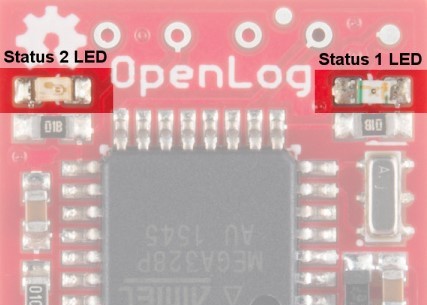
The OpenLog has two LEDs; Status 1 LED and Status 2 LED. It is very important to understand what these two status LEDs are signalling, especially the Status 1 LED.
- Status 1 LED : Used to display the UART serial activity.
- This LED flashes each time data is transferred between the devices across the UART serial channel.
- If the LED blinks three times on startup it means that the MicroSD card has failed to initialise.
- Status 2 LED : This LED blinks when the OpenLog is writing its buffer to the MicroSD card. This happens very quickly.
It's important to understand the function of the Status 1 LED. It gives the best indication that the OpenLog is logging the data sent to it from the microcontroller.
https://learn.sparkfun.com/tutorials/openlog-hookup-guide/allWhen the OpenLog is powered up for the very first time it will create two files on the MicroSD card; config.txt and LOG00000.txt.
The OpenLog has two different user selectable file modes:
- New File Logging
- This mode creates a new file each time OpenLog powers up. The initial file is the LOG00000.txt noted above.
- Each new log file increments the number; LOG00001.txt then LOG00002.txt and so on.
- This logging file mode is the system default but can be changed in the config.txt file by the user - discussed below.
- Append File Logging
- This file creates a file called SEQLOG.txt if not already on the MicroSD card.
- All data from the current session and all the following sessions will be appended to this single file.
- This mode is user selectable by editing the config.txt file - discussed below.
The config.txt file created by the OpenLog on its very first power up contains two lines that can be edited with any text editor:
9600,26,3,0,1,1,0
baud,escape,esc#,mode,verb,echo,ignoreRX
The first line contains the configuration settings and the second line are the setting descriptors. After editing the configuration file it is necessary to power cycle the OpenLog to force the changes.
The items marked up in red is the file mode option and the acceptable values are:
- 0 : New File Logging (default)
- 1 : Append File Logging
- 2 : The OpenLog will startup in Command Mode - discussed below. This option will rarely be used.
The default baud rate is 9600. This is suitable for almost any logging activity so would rarely be needing to be changed. The baud rate can be edited in the configuration file. Acceptable values are: 2400, 4800, 9600, 19200, 38400, 57600 and 115200.
Reading the Log FilesThe log files produced by the OpenLog are text files that can be opened by any text editor on a computer.
A word of warning though. The MicroSD card should be connected to the computer using a USB card reader that has a MicroSD card slot.
Don't use one of those SD card blanks and the internal card reader of the computer because this combination often returns the error “Can't save to the Micro SD Card ” when attempting to write to the card e.g. to format it or remove old log files.
Command Mode
The OpenLog has a Command Mode. This is not a feature that would often be used with a microcontroller so the discussion here will be brief.
A microcontroller can send the sequence to enter Command Mode and then issue commands. However the microcontroller must be able to anticipate and parse the OpenLog responses. Any modifications to the Command Mode by updating the OpenLog's firmware would potentially break a MicroPython driver that had methods for accessing this mode.
Command Mode allows a user on a computer to issue simple file operating system style commands. Such commands include:
- File operations
- Create a new file
- Append text at an offset to a file
- Delete a file
- Directory operations
- Create a subdirectory
- List the contents of the current directory
- Change to a subdirectory
- Delete a subdirectory
- System settings - all the settings available in the config.txt configuration file can also be changed here.
If it becomes necessary to use Command Mode (e.g. to reset the log file numbering back to 00000) then it's best done by connecting the OpenLog to a computer.
Connecting the OpenLog to a computer requires only a serial to USB converter (cost: about US1$) and a serial console program such as PuTTY (for Windows).
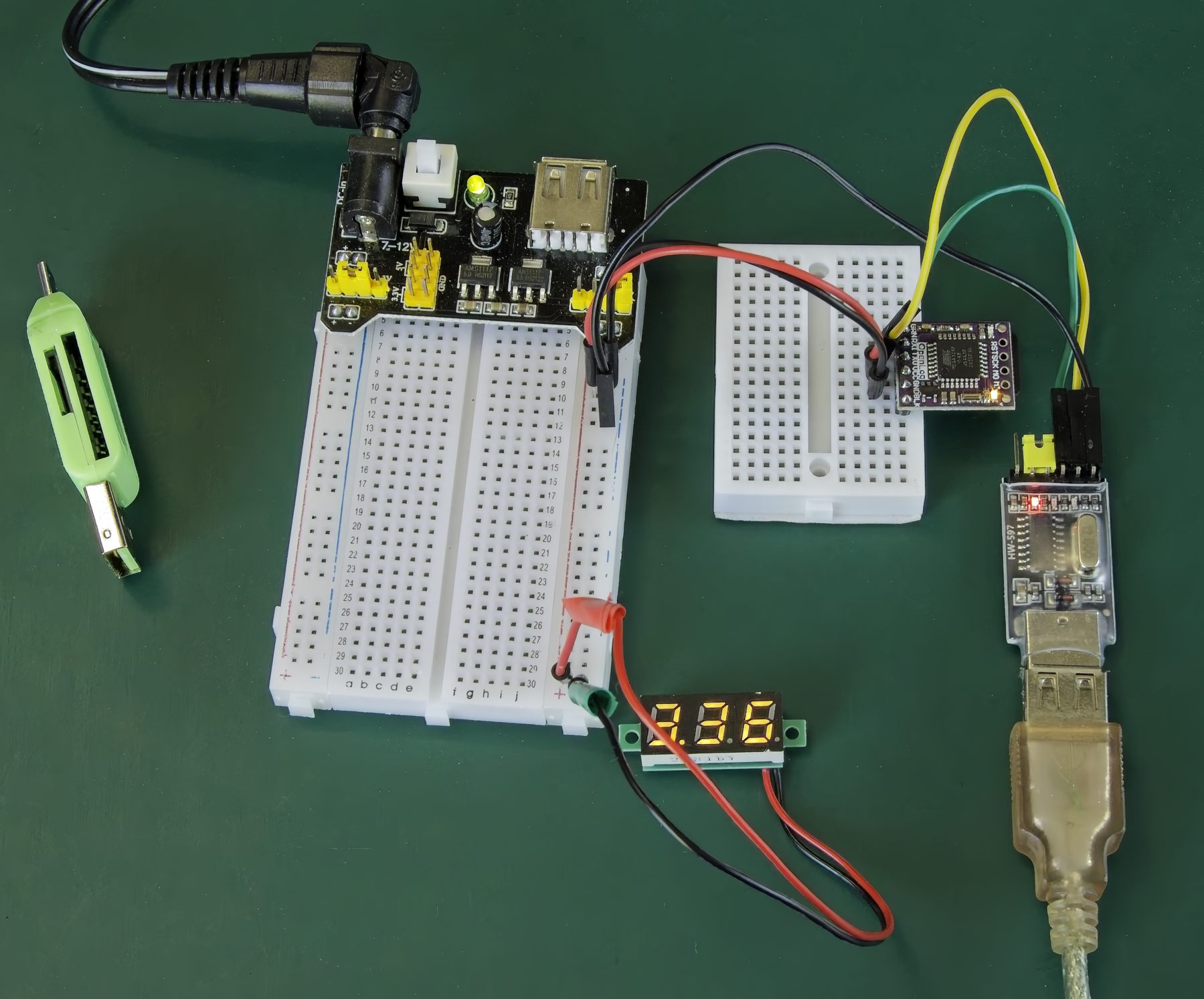
The Tx and Rx pins between the OpenLog and the serial to USB converter must be crossed. The screenshot below shows a PuTTY session on a Windows computer. At the console type Ctrl-Z (ASCII 26) three times to enter Command Mode.
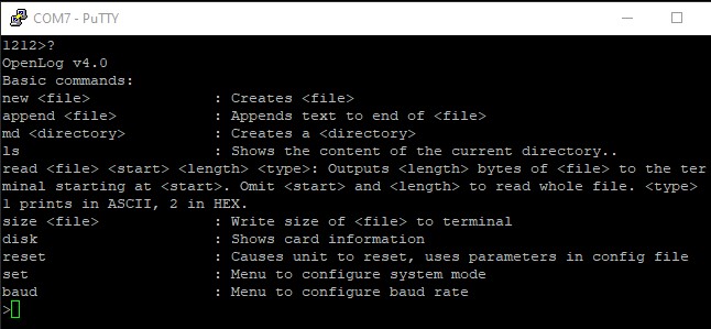
The OpenLog will send a list of available commands if a '?' is entered at the console.
OpenLog MicroPython Driver for micro:bit
The OpenLog MicroPython driver written to accompany this article provides methods for the following:
- A class constructor that assigns the micro:bit's pins to connect with the OpenLog, initialises the UART interface and resets the OpenLog ready to receive logging data.
- Write binary data streams to the OpenLog.
- Write lines of strings, integers and float values to the OpenLog.
- Write strings, integers and floats to a text file in comma separated format. This allows easy importing into spreadsheets.
- Return the status of the OpenLog.
- Redirect the UART from the OpenLog back to the REPL.