DS1302 Real Time Clock
Contents
DS1302 Description
Compared to other realtime clock (RTC) chips the DS1302 could be considered as quite basic but easy to use. The datasheet describes it as as a trickle-charge timekeeping chip
. The chip has a configurable trickle charger on board, useful if a rechargeable backup battery is being used.

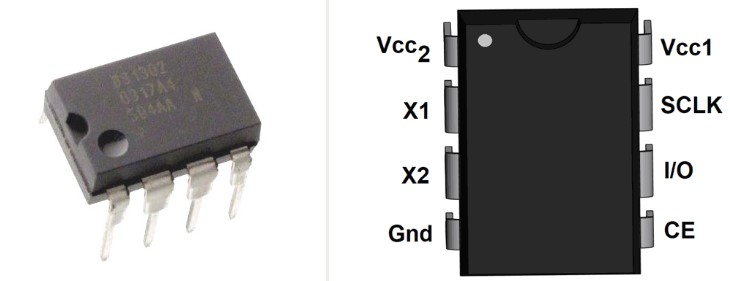
The DS1302 has 8-pins and is available in PDIP (Plastic Dual Inline Package) or a choice of two sizes in SO (Small Outline) packaging. The chip pinout and packaging details can be found in the product datasheet.
It operates in the wide voltage range of 2.0V to 5.5V, making it suitable for both 3.3V microcontrollers (e.g. micro:bit) and 5V microcontrollers (e.g. Arduino).
The DS1302 does't have an alarm or a countdown timer. It really is just a timekeeping clock and calendar.
The DS1302 requires an external 32.768 Khz crystal for its oscillator circuit that provides the "clock tick".
The clock accuracy is dependent upon several factors:
- Accuracy of the crystal.
- Routing from the chip pins should be kept away from the crystal.
- Crystal frequency drifts with changing temperature. Unlike the more sophisticated DS3231 RTC chip there is no automatic temperature compensation of the crystal frequency.
The clock counts seconds, minutes, hours, day of the week, day, month and year (with leap-year compensation).
The DS1302 has 31 bytes of non-volatile RAM that is not used by the clock itself but rather, is available for general use by the user.
DS1302 Breakout Board
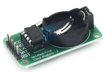
Rather than just using the bare chip, it's usually much more convenient for the hobbyist to purchase the DS1302 on a breakout board. FIG 1 shows such a board, universally available for a (very) few dollars.


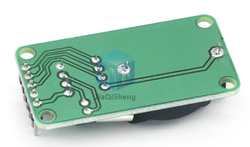
Fig 2 - Both sides of the DS1302 breakout board
Note the simplicity of the breakout board. The DS1302 chip doesn't require any external resistors or capacitors so there are none on the board.
There is provision on the board for a backup battery. The CR2032 battery is often used.The DS1302 draws such a low current (especially so in backup mode) this button cell battery can hold the clock keeping function up for a decade or more when the main power source is unavailable.
The trickle-charge circuit is off by default when the DS1302 powers up. It is considered uneconomical to go to the expense of a rechargeable backup battery so the charge circuit will rarely be used. It will not be discussed further in this article. No trickle-charge control functions are provided in the MicroPython driver.
.jpg)
DS1302 Breakout Board Pinout
The following pins of the DS1302 chip are brought out on the module board:
- GND - connect to GND on the micro:bit.
- VCC - Connect to 3.3V on the micro:bit.
- CLK - Clock signal, connect to pin13 on the micro:bit.
- DAT - Bidirectional data line has an internal 40kΩ pulldown resistor. Connect to pin14 on the micro:bit.
- RST - Chip Enable (CE) pin; connect to pin15 on the micro:bit.
The CLK, DAT and RST pins on the module can be connected to any available digital pins on the micro:bit. However the suggested pin assignments above are the defaults for the MicroPython driver discussed below.
The DS1302 Clock
The DS1302 clock has seven date/time registers that can be written and read via a three wire SPI type serial interface. These registers are accessible at anytime after the DS1302 is fully powered up:
- Seconds (00 - 59)
- Minutes (00 - 59)
- Hour (00 - 23)[2]
- Day of Week (01 - 07)
- Calendar Day (01 - 31)
- Month (01 - 12)
- Year (00 - 99)
The Day of Week can be set to start on any week day. At midnight the Day of Week is incremented. After the seventh day, it wraps back to 1. This is equivalent to the WEEKDAY concept in Microsoft Excel.
The contents of the time and calendar registers are in BCD (binary coded decimal) format. BCD is widely used in digital electronics.
In BCD, each decimal digit (0 to 9) is converted into a four-digit binary code (0's and 1's).This makes for very easy and efficient conversion between decimal and binary representations[3].
The 3-Wire SPI Interface
All data transfers are initiated by driving the RST (CE) pin HIGH. The CLK pin must be low at this stage.
The CLK pin is used to clock each bit. One bit of data is transferred on each clock cycle. A clock cycle is a rising edge to HIGH followed by a falling edge to LOW.
The bits of a byte are transferred from LSB (bit 0) to MSB (bit 7). The following is pseudocode for the transfer of one byte (8 bits):
Write a byte to the DS1302
Set RST = HIGH
For n = 0 to 7:
  Set DAT = bit(n)
  Set CLK= HIGH
  Set CLK = LOW
Set RST = LOW

Read a byte to the DS1302
Set RST = HIGH
For n = 0 to 7
  Set bit(n) = DAT
  Set CLK= HIGH
  Set CLK = LOW
Set RST = LOW
There are no timing steps required during the data transfer loop.
Reading and Writing Clock Registers
Reading and writing to the clock registers is a very simple two step process:
- Write the register address using the algorithm given above. The register addresses are given in Table 3 (page 9) of the datasheet.
Note that the read address of a register is different to the write address of the same register. This is how the DS1302 determines whether data is to be either written or read to/from the register
For example: the Seconds register write address is 0x80 while its read address is 0x81. - Using the algorithms given above either write a byte of data or read a byte of data from the DS1302.
Reading and Writing to the RAM
The DS1302 has 31 bytes of static RAM for the exclusive use by the user. Since it is non-volatile, values written to the RAM registers will survive the complete powering down of the board.
Reading and writing to the RAM follows the same process for accessing the clock registers. The RAM register addresses can also be found in Table 3.
Each of the 31 RAM registers are 8-bits in width therefore values written must be in the range of 0 to 255.
MicroPython Driver for micro:bit
The original driver written by Shaoziyang can be found on GitHub (https://github.com/shaoziyang/microbit-lib/tree/master/misc/DS1302). This driver is well-coded.
An extended version has been developed as part of this series on MicroPython for the microbit. This page also provides a detailed description of the driver's methods with sample code.
The driver is implemented as a class. This is by far the most versatile approach as a program can use the class to instantiate more than one physical DS1302 module, all independent of each other. It is also easy for a knowledgeable user to extend the class.
Constructor
The driver provides a constructor to instantiate DS1302 objects. It is here that the user can change the digital pin assignments for the micro:bit if desired.
Reading and Setting the Clock
Methods are provided to set and read the seven time and date registers. Methods are available to obtain the time and date in formatted strings that Microsoft Excel recognises. This makes it easier to import logged data into Excel for further analysis.
Reading and Writing to the RAM
A very simple method is provided to read and write values to the onboard DS1302 RAM.