DS3231 Real Time Clock
Contents
DS3231 Description
The datasheet describes the DS3231 as a low-cost, extremely accurate I2C real-time clock (RTC) with an integrated temperature compensated crystal oscillator (TCXO) and crystal.
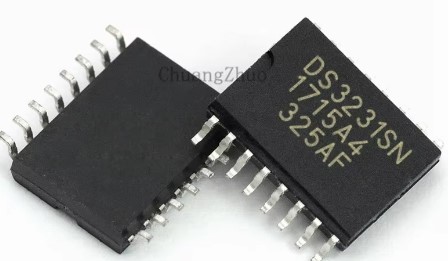
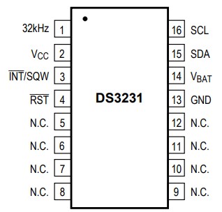
The DS3231 has 16-pins though eight of these aren't connected (NC). It is available in SO (Small Outline) packaging only. The chip pinout and packaging details can be found in the product datasheet. The datasheet also advises that the eight NC pins should all be connected to ground.
It operates in the wide voltage range of 2.3V to 5.5V, making it suitable for both 3.3V microcontrollers (e.g. micro:bit) and 5V microcontrollers (e.g. Arduino).
The DS3231 has an internal crystal, unlike the DS1302 and DS1307 with their external crystals. For this reason the DS3231 is much more accurate than the latter two. The DS3231 datasheet claims an accuracy of ±2 minutes per year.
As do many RTC chips the DS3231 crystal operates at a frequency of 32.768 kHz. This is equivalent to 215 cycles per second making it easy to interface with simple counting chips. It's very easy to reduce this frequency down to 1Hz; a time interval of one second.
The time and date is set and read through an industry standard I2C Interface.
DS3231 Breakout Board
Rather than just using the bare chip, it's usually much more convenient for the hobbyist to purchase the DS3231 on a breakout board. FIG 1 shows such a board, widely available for a (very) few dollars.
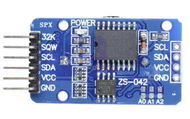
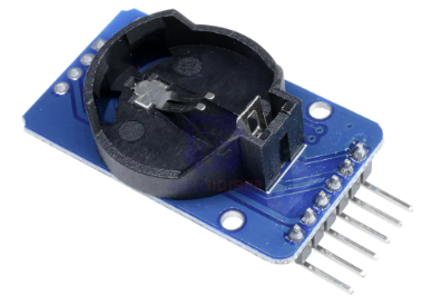
Fig 1 - Both sides of the DS3231 breakout board
There is provision on the back of the board for a backup battery. Unfortunately this board expects a rechargeable Li-ion battery such as the LIR2032. There are numerous online reports that the charge circuit on this board is also not fit for even this battery. If a standard 3V CR2032 battery is substituted there could/will eventually be an explosion!
There are also many online references that suggest the problem can be remedied by removing the 200 Ω resistor. There are also suggestions that since the micro:bit operates at 3.3V it is not able to charge the 3.6V LIR2032 in any case. The recommendation here is to consider not using a backup battery unless your project really requires it. You should seek your own independent advice before attempting to do so.
AT24C32 EEPROM
The larger 16-pin chip on the board is the DS3231. The smaller 8-pin chip is an AT24C32 EEPROM. This is not part of the RTC functionality; it's provided purely for the user to store custom non-volatile data. The datasheet for the AT24C32 states that it is good for one million write cycles. While given that, it is not considered good practice to continually write to an EEPROM, for example using it as a logger for rapidly collected sensor data.
The AT24C32 provides 4KB of non-volatile memory. It is accessed by the same onboard I2C interface that's used to communicate with the DS3231. It has a default address of 0x57 on this board but that can changed by soldering combinations of the jumper pads A0, A1 and A2.
The driver provided with this webpage does not cover the AT24C32, so it will not be discussed further.
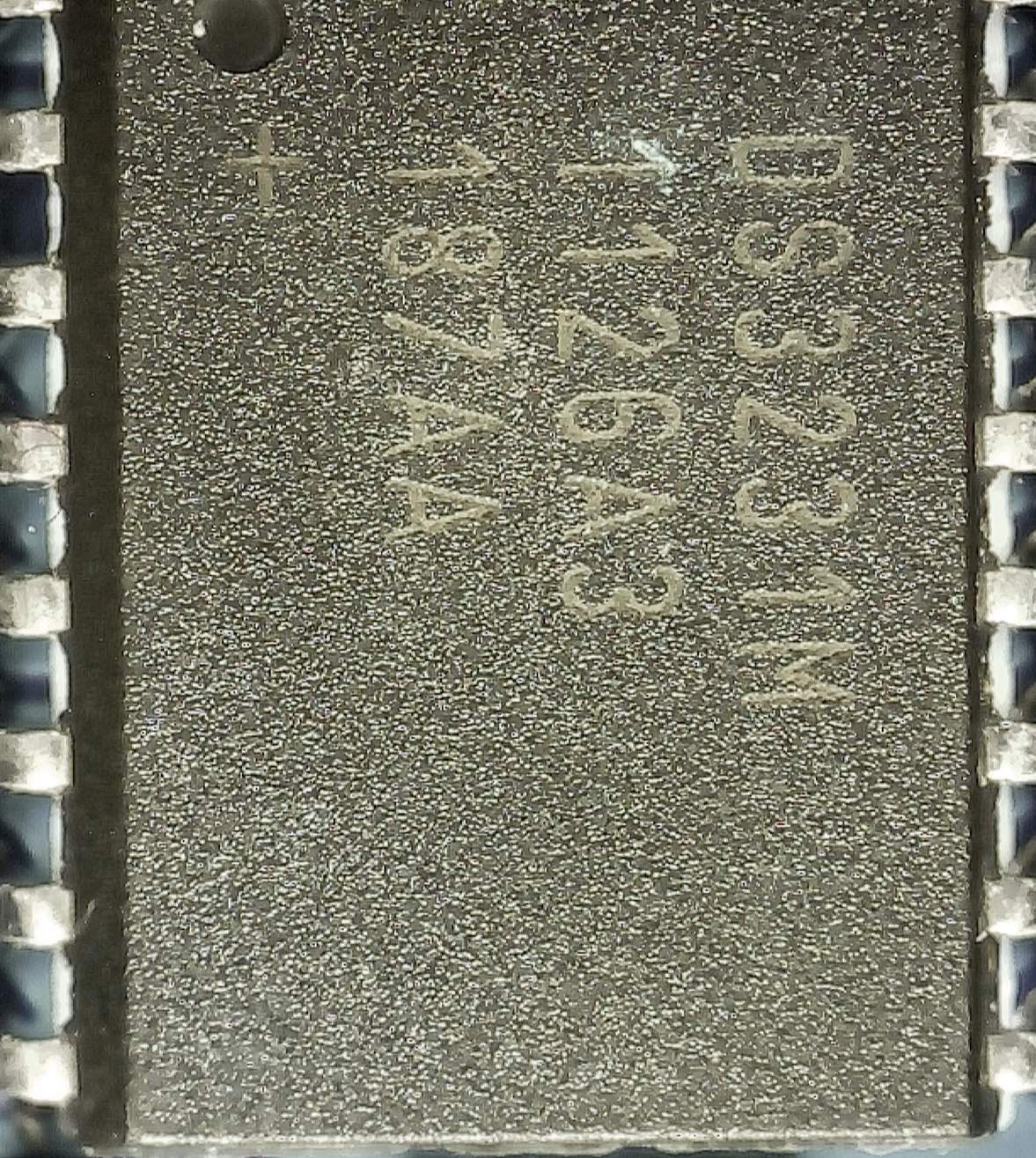
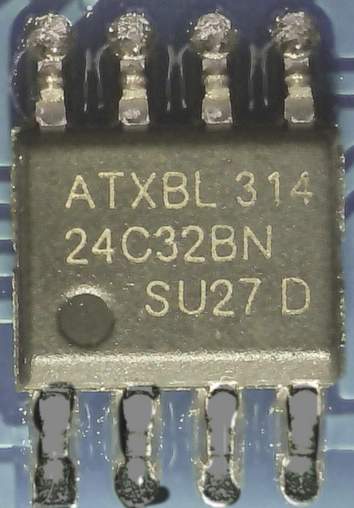
Fig 2 - Micrograph view of DS3231 and AT24C32 chips on the breakout board
DS3231 Breakout Board Pinout
The following pins of the DS3231 chip are brought out on the module board:
- GND - connect to GND on the micro:bit
- VCC - Connect to 3.3V on the micro:bit
- SDA - I2C data line, connect to pin20 on the micro:bit
- SCL - I2C clock signal, connect to pin19 on the micro:bit
- SQW - Alarm interrupt signal (default) or outputs a programmable square wave; connect this to any spare digital pin on the Micro:bit eg pin0
- 32K - access to the DS3231's crystal frequency
The pins on the other end of the board (SCL, SDA, VCC and GND) allows daisy chaining of another I2C slave.
The DS3231 Clock
The DS3231 clock has registers that can be written and read via I2C for:
- Seconds (00 - 59)
- Minutes (00 - 59)
- Hour (00 - 23)[1]
- Day of Week (01 - 07)
- Calendar Day (01 - 31)
- Month (01 - 12)
- Year (00 - 99)
The Day of Week can be set to start on any week day. At midnight the Day of Week is incremented. After the seventh day it wraps around to Day of Week = 1. This is equivalent to the WEEKDAY concept in Microsoft Excel.
There is a Century bit (Bit7 of the Month register!) that is initially set to 0. After the year = 99 has exceeded Dec 31, this bit is set to 1 and the year wraps around to 0. The driver described below ignores the century bit.
The contents of the time and calendar registers are in BCD (binary coded decimal) format. BCD is widely used in digital electronics.
In BCD, each decimal digit (0 to 9) is converted into a four-digit binary code (0's and 1's).This makes for very easy and efficient conversion between decimal and binary representations[2].
The DS3231 Alarms
The DS3231 provides two independently programmable time/date alarms; Alarm 1 and Alarm 2. These alarms are overly complicated (in our view) to use. There are many online blogs testifying to user frustration when trying to use them.
Alarm 1
Alarm 1 allows an alarm condition to be set with seconds, minutes, hour, day of month/day of week configured.
Additionally the alarm can be configured to repeat:
- Once every second
- When seconds match alarm condition
- When seconds and minutes match alarm condition
- When hours, minutes and seconds match alarm condition
- When day of month, hours, minutes and seconds match alarm condition
- When day of week, hours, minutes and seconds match alarm condition
Alarm 1 has four registers that can be written to (and also read) in order to set the alarm condition. The desired level of alarm repeat is configured by the combined values of Bit7 of the four registers. See the DS3231 datasheet for details.
Alarm 2
Alarm 2 is similar to Alarm 1 but doesn't allow configuration of the alarm condition down to seconds resolution. This means that it can't be triggered to fire every second. Instead it can be set to repeat every minute when the clock's seconds = 0.
Alarm 2 has three registers that can be written to (and also read) in order to set the alarm condition. The desired level of alarm repeat is configured by the combined values of Bit7 of the three registers. See the DS3231 datasheet for details.
Detecting an Alarm
The Status Register has a bit for each alarm that is pulled HIGH when the associated alarm is triggered on the alarm conditions being met. Note that the alarm status bit is latched HIGH. It is the responsibility of the user program to reset this bit LOW else an alarm repeat will not be detected.
The SQW pin can be set as an interrupt that is pulled LOW when either alarm fires. This pin is latched LOW but resets to HIGH when the a 0 is written to the alarm bit in the Status Register.Temperature Sensor
The DS3231 has an onboard temperature sensor that is automatically used by the chip to read the temperature every 64 seconds. The temperature reading is used to temperature compensate the crystal oscillator circuit.
The temperature sensor is also available to the user. The user can force the DS3231 to take a temperature measurement reading at anytime but this approach can be tricky because the BSY status bit in the Status Register needs to be monitored through the process.
Unless a rapid series of temperature readings are required it is much simpler to use the last system automatically generated temperature reading.
The temperature measurement is stored as a 10-bit value across two 8-bit registers. The MSB (most significant byte) contains the whole integer part in two's complement format.
The fractional part is found in Bit[7:6] of the LSB (least significant byte). The algorithm to combine the two parts to derive the float type temperature value is simple and well explained in the DS3231 datasheet.
The Rest
This section describes several other features of the DS3231. They are not available in the driver described in the next section.
Access to the Clock's Oscillator
The 32K pin on the breakout board gives access to the crystal driven oscillator clock frequency of 32.768 kHz.
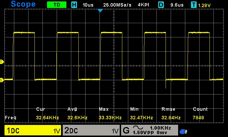
Programmable Square Wave
If the SQW pin doesn't need to be used as an alarm interrupt it can be programmed to output a square wave at a divided frequency of the main chip oscillator. The following frequencies can be selected:
- 1Hz
- 1.024 kHz
- 4.096 kHz
- 8.192 kHz (default)
The frequency is selected by writing values to Bit4:3 of the Control Register.
Aging Offset
The Aging Offset register takes a user-provided value that's used as a parameter to fine tune the algorithm used for temperature compensating the main oscillator frequency. Most hobbyists will not be concerned with this but if interested it is explained in more detail in the DS3231 datasheet.
MicroPython Driver for micro:bit
The original driver written by Shaoziyang can be found on GitHub (https://github.com/shaoziyang/microbit-lib/tree/master/misc/DS3231). This driver is well-coded.
An extended version has been developed as part of this series on MicroPython for the microbit. This page also provides a detailed description of the driver's methods with sample code.
The driver is implemented as a class. This is by far the most versatile approach as a program can use the class to instantiate more than one physical DS3231 module, each independent of the other. It is also easy for a knowledgeable user to extend the class.
Constructor
The driver provides a very simple constructor to instantiate DS3231 objects.
Reading and Setting the Clock
Methods are provided to set and read the seven date and time registers. Methods are available to obtain the time and date in formatted strings that Microsoft Excel recognises. This makes it easier to import logged data into Excel for further analysis.
Using the Alarm
Only Alarm 2 is implemented. It can be set to repeat each minute or on a minute/hour combination. A method is provided to detect if the alarm has met the set alarm condition. Another method is available to reset the alarm so that a repeat alarm event can be detected.
Temperature
Finally, there is a method that returns the last system initiated temperature reading.