PCF8563 Real Time Clock
Contents
PCF8563 Description
The datasheet describes the PCF8563 as a CMOS Real-Time Clock (RTC) and calendar optimised for low power consumption.


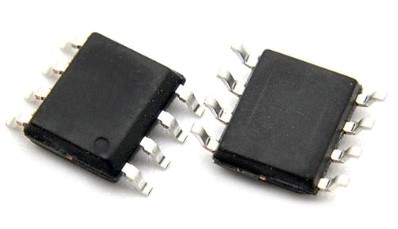
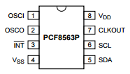
Fig 1 - PCF8563 real-time clock chip with its pinout
The PCF8563 is available in three different packages from NXP Semiconductors, the original developers:
- HVSON10; Plastic thermal enhanced very thin small outline package with 10 terminals. Two of the terminals are not connected (NC) and shouldn't be used.
- SO8; Plastic small outline package with 8 pins.
- TSSOP8; Plastic thin shrink small outline package with 8 pins.
The PCF has been cloned by other manufacturers and is readily available in forms such as PDIP (Plastic Dual Inline Package) 8-pin.
It operates in the very wide voltage range of 1.0V to 5.5V, making it suitable for both 3.3V microcontrollers (e.g. micro:bit) and 5V microcontrollers (e.g. Arduino).
The PCF8563 requires an external crystal with a frequency of 32.768 kHz. This reduces the clock accuracy compared to the DS3231 RTC with its internal crystal.
The time and date is set and read through an industry standard I2C Interface.
PCF8563 Breakout Board
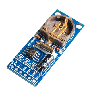
Rather than just using the bare chip, it's usually much more convenient for the hobbyist to purchase the PCF8563 on a breakout board. FIG 1 shows such a board, widely available for a (very) few dollars.


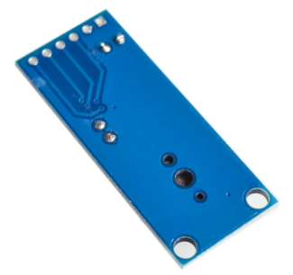
Fig 2 - Both sides of the PCF8563 breakout board
There is provision on the back of the board for a CR1220 backup battery. As is the case for other RTCs the PCF8563 has an extremely low current draw (typically 0.25 μA). So this battery is quite small it could maintain the clock function for several years if the main supply is lost.
.jpg)
PCF8563 Breakout Board Pinout
The following pins of the PCF8563 chip are brought out on the module board:
- GND - connect to GND on the micro:bit.
- VCC - Connect to 3.3V on the micro:bit.
- SDA - I2C data line, connect to pin20 on the micro:bit.
- SCL - I2C clock signal, connect to pin19 on the micro:bit.
- INT - Alarm interrupt signal; optionally connect this to any spare digital pin on the micro:bit eg pin0.
- COT - Access to the PCF8563's crystal frequency, not used by the driver.
The I2C Interface
The I2C interface is compliant with the international written standard and has a maximum bus speed of 400 kbit/sec. The bus slave address is 0x51. This has been fixed at the point of manufacture and is not changeable by the user.
The register address is automatically incremented after each read or write. This means that more than one byte can be read or written in a single operation.
Reading and writing to registers is an easy task.
Writing Data to the PCF8563
Assemble a buffer (usually a bytearray) where the first byte is the register address. One or more bytes of data are then appended to the register address in the buffer. The entire buffer is written to the PCF8563 in a single operation.
Reading Data from the PCF8563
Write the register address to the PCF8563. Read one or more bytes from the PCF8563 into a buffer.
The PCF8563 Clock
The PCF8563 clock has seven registers that can be written and read via I2C for:
| Register | Address | Values | Bits Used |
|---|---|---|---|
| Seconds | 0x02 | 0 to 59 | bits[6:0] |
| Minutes | 0x03 | 0 to 59 | bits[6:0] |
| Hours | 0x04 | 0 to 23 | bits[5:0] |
| Days | 0x05 | 1 to 31 | bits[5:0] |
| Weekdays | 0x06 | 0 to 6 | bits[2:0] |
| Months | 0x07 | 1 to 12 | bits[4:0] |
| Years | 0x08 | 0 to 99 | bits[7:0] |
As shown in the table of calendar and time registers above, not all bits are used in most of the registers. When reading the registers it is essential to mask out the bits not used as it is not guaranteed that they will all be a 0. Failure to mask out the unused bits will lead to unexpected results.
It is also important to note that the PCF8563 operates only in 24-hour time. If a 12-hour time is required then the user program will need to do the (simple) conversion.
The Day of Week can be set to start on any week day. At midnight the Day of Week is incremented. After the seventh day it wraps around to Day of Week = 0. This is equivalent to the WEEKDAY concept in Microsoft Excel.
There is a Century bit (Bit[7] of the Month register!) that is initially set to 0. After the year = 99 has exceeded Dec 31, this bit is set to 1 and the year wraps around to 0. The driver described below ignores the century bit.
The contents of the time and calendar registers are in BCD (binary coded decimal) format. BCD is widely used in digital electronics.
In BCD, each decimal digit (0 to 9) is converted into a four-digit binary code (0's and 1's).This makes for very easy and efficient conversion between decimal and binary representations[1].
The PCF8563 Alarm
The PCF8563 provides one programmable time/date alarm. It is somewhat simpler to use than (for example) the DS3231 alarms.
Setting the alarm
There are four alarm registers with values coded in BCD:
- Minute_alarm : 0 to 59
- Hour_alarm : 0 to 23
- Day_alarm : 1 to 31
- Weekday_alarm : 0 to 6
On each alarm register, the bit[7] is reserved to enable (0) or disable (1) the register. A repeating alarm can be set using any or all combinations of these registers. The MicroPython driver described below only uses the Minute_alarm and Hour_alarm registers.
Detecting an Alarm
The Control_status_2 register bit[3] is pulled HIGH when the alarm is triggered on the alarm conditions being met. Note that the alarm status bit is latched HIGH. It is the responsibility of the user program or driver to reset this bit LOW else an alarm repeat will not be detected.
Additionally - the MicroPython driver discussed below sets the INT pin as an interrupt that is pulled LOW when the alarm "fires". This pin is latched LOW but resets to HIGH when a 0 is written to the alarm bit in the Control_status_2 register.
The PCF8563 Countdown Timer
A useful feature found on the PCF8563 is a simple countdown timer. It is controlled from three registers:
- Timer_control (0x0E)
- Timer (0x0F)
- Control_status_2 (0x01)
The Timer register accepts a starting value in the range 0 to 255 which is counted down by a timer "clock tick"
The Timer_control register has bits that provide two functions:
- Bit[7] enables (1)/disables (0) the timer
- Bit[1:0] sets the frequency of the timer "clock tick"
- 00 = 4.096 kHz
- 01 = 64 Hz
- 10 = 1 Hz (i.e. 1 second interval)
- 11 = 1⁄60 Hz (i.e. 1 minute interval)
The MicroPython driver for the micro:bit discussed below only uses the third option i.e. counts down in seconds.
The Control_status_2 register bit[2] is pulled HIGH when the countdown from the initial value has reached 0. Note that this timer status bit is latched HIGH. It is the responsibility of the user program or driver to reset this bit LOW else a countdown repeat will not be detected.
Additionally - the MicroPython driver discussed below sets the INT pin as an interrupt that is pulled LOW when the countdown completes". This pin is latched LOW but resets to HIGH when a 0 is written to the timer bit in the Control_status_2 register.
Using the timer
So, in summary; the basic algorithm for using the countdown timer is:
- Set the initial value in the timer register.
- Set the timer clock frequency in the Timer_control register (e.g. 1 second).
- Turn on the countdown timer by setting bit[7] in the Timer_control register.
- Monitor bit[2] of the Control_status_2 register for the countdown to complete.
- Reset bit[2] of the Control_status_2 register so that the next countdown event can be detected.
MicroPython Driver for micro:bit
The well written DS3231 MicroPython driver by Shaoziyang (found on GitHub https://github.com/shaoziyang/microbit-lib/tree/master/misc/DS3231) was used as a template to develop a driver for the PCF8563. This code base was adapted to the PCF8563 register structure.
It was extended to cover the countdown timer and also provides better date and time formatting methods. This extended version has been developed as part of this series on MicroPython for the microbit. This page also provides a detailed description of the driver's methods with sample code.
The driver is implemented as a class. This is by far the most versatile approach as a program can use the class to instantiate more than one physical PCF8563 module, each independent of the other. It is also easy for a knowledgeable user to extend the class.
Constructor
The driver provides a very simple constructor to instantiate PCF8563 objects.
Reading and Setting the Clock
Methods are provided set and read the seven time and date registers. Methods are available to obtain the time and date in formatted strings that Microsoft Excel recognises. This makes it easier to import logged data into Excel for further analysis.
Using the Alarm
The alarm can be set to repeat on any:
- Minute only
- Hour only
- Minute/Hour combination i.e a given time
A method is provided to detect if the alarm has "triggered". Another method is available to reset the alarm so that a repeat alarm event can be detected.
Countdown Timer
The timer counts down in seconds from an initial starting value in the range of 1 to 255.
The driver class provides countdown timer methods to:
- Set the timer starting value.
- Turn the timer on or off.
- Detect if a countdown has completed.
- Clear the timer if the countdown has completed.