TCA9548A I2C Multiplexer
Contents
What is an I2C Multiplexer?
The I2C serial protocol has much going for it. While it is relatively slow compared to some other communication protocols it is inexpensive, robust, easy to use and has a written international standard. As a consequence of being widely used I2C has a well developed software support base.
The standard allows many I2C slaves to share a single master controlled bus. The slaves are identified by and respond to a unique 7-bit (sometimes 10-bit) address. Herein lies one of the few issues with I2C. Each device on the bus must have a unique address.
Some slave devices provide mechanisms to choose from a pool of addresses. However many don't have this option as the address is fixed at the point of manufacture.
Often it is desirable to have more than one of the same type of e.g. sensor on the same bus. The solution is to use an I2C multiplexer. These allow each slave with a clashing address to be selectively "switched" on or off from the serial bus.
Two popular I2C multiplexer chips are the PCA9548A and TCA9548A chips. The older NXP Semiconductor's PCA9548A is almost functionally the same as the newer Texas Instruments Incorporated's TCA9548A chip. The main difference is the TCA9548A can be powered by a slightly larger voltage range than the PCA9548A.
Both chips can be considered interchangeable in the context of the discussion on this webpage.
TCA9548A Multiplexer Description
The TCA9548A is described in the product datasheet as a device that has eight bidirectional translating switches that can be controlled through the I2C bus.
Ok, what does that mean?
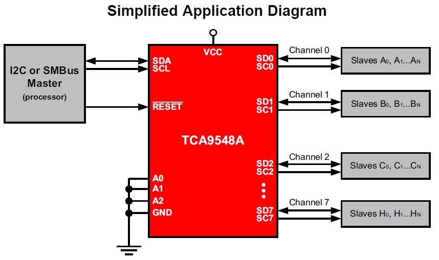
Firstly, the TCA9548A is a slave that is controlled through the microcontroller's I2C bus. Additionally it has eight 'client' I2C channels. Each channel can host one or more I2C slaves and can be opened or closed with respect to the microcontroller.
The microcontroller can control the state (opened or closed) of each of these channels very simply by writing to a control register on the TCA9548A. This means that by selectively opening and closing channels the microcontroller is able to communicate with up to eight I2C slaves that all have the same address.
This ability to manage multiple I2C devices, all with the same address and on the same bus, is known as multiplexing . The following diagram from the Texas Instruments' product datasheet explains it well.

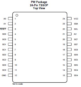
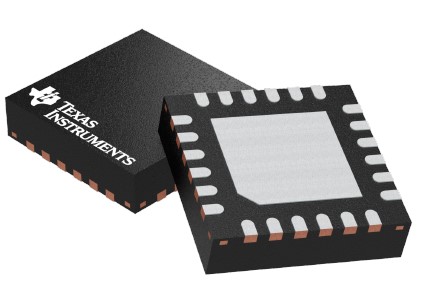
The TCA9548A chip is available in two different packages; TSSOP[1] (7.8mm x 4.4mm x 1.2mm) and VQFN[1] (4.0mm x 4.0mm x 1mm). Both have 24 pins/tabs. The TSSOP form is the one usually found on breakout boards.


Fig 1 - TCA9548A (from the datasheet): [L] TSSOP package shape and pinout, [R] VQFN-package form.
Pin Configuration and Functions
| Pin | Description |
|---|---|
| VCC | Supply voltage (1.65V - 5.5V) |
| GND | Ground |
| A0 | Configure I2C address |
| A1 | Configure I2C address |
| A2 | Configure I2C address |
| RESET | Pull LOW for soft reset |
| SCL | Serial clock, connected to microcontroller's SCL |
| SDA | Serial data, connected to microcontroller's SDA |
| SC0 SD0 |
Channel 0 serial clock, connect to I2C slave SCL Channel 0 serial data, connect to I2C slave SDA |
| SC1 SD1 |
Channel 1 serial clock, connect to I2C slave SCL Channel 1 serial data, connect to I2C slave SDA |
| SC2 SD2 |
Channel 2 serial clock, connect to I2C slave SCL Channel 2 serial data, connect to I2C slave SDA |
| SC3 SD3 |
Channel 3 serial clock, connect to I2C slave SCL Channel 3 serial data, connect to I2C slave SDA |
| SC4 SD4 |
Channel 4 serial clock, connect to I2C slave SCL Channel 4 serial data, connect to I2C slave SDA |
| SC5 SD5 |
Channel 5 serial clock, connect to I2C slave SCL Channel 5 serial data, connect to I2C slave SDA |
| SC6 SD6 |
Channel 6 serial clock, connect to I2C slave SCL Channel 6 serial data, connect to I2C slave SDA |
| SC7 SD7 |
Channel 7 serial clock, connect to I2C slave SCL Channel 7 serial data, connect to I2C slave SDA |
Breakout boards generally expose all these pins.
I2C Address Selection
The A0, A1 and A2 pins enable the user to select from eight possible I2C addresses. These pins, in any combination, are connected to GND through pulldown resistors or VCC through pullup resistors. The following table shows the combinations that allows an address range of 0x70 through 0x77.
| A2 | A1 | A0 | Address |
|---|---|---|---|
| GND | GND | GND | 0x70 |
| GND | GND | 3.3V | 0x71 |
| GND | 3.3V | GND | 0x72 |
| GND | 3.3V | 3.3V | 0x73 |
| 3.3V | GND | GND | 0x74 |
| 3.3V | GND | 3.3V | 0x75 |
| 3.3V | 3.3V | GND | 0x76 |
| 3.3V | 3.3V | 3.3V | 0x77 |
Using the TCA9548A Multiplexer
The TCA9548A has a bidirectional I2C standardised interface controlled by a master (usually a microcontroller) and can operate in Standard Mode (0 - 100kHz) and Fast Mode (0 - 400kHz).
There is only a single register (known as the Control Register) available for the user to read or write to through the I2C bus. This makes this device incredibly easy to use.
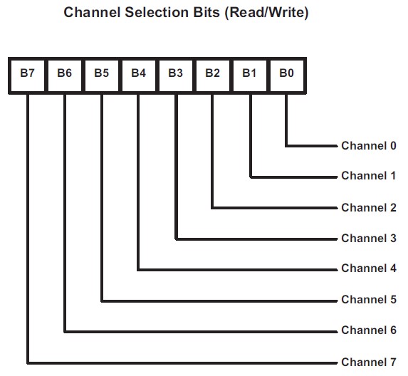
The Control Register is 8-bits with each bit controlling one channel. The following diagram (Texas Instruments, TCA9548A Datasheet, p18) illustrates the concept.

If the bit value = 1, then that channel is open. Conversely, if the bit value = 0, then that channel is closed.
As an example if the contents of the Control Register were 0b00000110 then Channel 1 and Channel 2 would be open with the other channels all closed.
As already mentioned, the TCA9548A has only one user accessible register. A register address is not used to access this Control Register. Updating the register in order to open or close channels is simply done by writing a byte on the I2C bus, addressed to the TCA9548A.
Similarly to read the status (opened or closed) of all the channels it is only necessary to read one byte from the I2C bus.
TCA9548A MicroPython Driver for the micro:bit
A simple to use TCA9548A MicroPython driver is available here. It is free to use, extend, etc but comes with no warranty!
The driver is implemented as a class. The class constructor allows the user to optionally provide:
- The I2C address (default is 0x70) of the TCA9548A.
- A digital pin on the micro:bit that is connected to the RESET pin of the TCA9548A.
The driver has methods for the following:
- Determine whether a channel is open
- Open one or more channels
- Close one or more channels
- Perform a soft rest of the TCA9548A (if the RESET pin is wired to a digital pin on the micro:bit)
Note: This driver is also fully compatible with the PCA9548A multiplexer chip.